Coatings are utilized for their ability to visually beautify and functionally protect many types of materials such as metals, woods and composites. Recent advances in specialty infrared reflective pigmentation technologies allow the coatings formulator, and thus the original equipment manufacturer or contractor, to impart an additional functionality to their products. This functionality enhances the overall value of the products. This functionality is the ability to reflect invisible heat energy while achieving a desired visible color. The reflection of heat energy results in a lower-temperature substrate when exposed to sunlight. The lower substrate temperature has a direct impact on reducing the cooling load in a building, for example, when used in a roof application. The higher infrared reflectivity of the substrate results in other benefits such as reduced warpage, reduced thermal cycling, reduced chemical degradation and the improved comfort of people in direct contact with the substrate.
Part two of this series discusses the science behind
infrared reflective pigmentation technology. In part three of the series, the
application of the technology will be reviewed.
Sunlight
Everyone is familiar with sunlight. Sunlight warms us and gives life the opportunity to flourish on Earth. It warms all objects directly or indirectly including: air, water, houses, cars, roads, animals, trees, grass and microorganisms. As a human being living on the earth, one comes to appreciate sunlight but may wish to mitigate its effects. Sunlight harbors harmful ultraviolet radiation that damages all types of substrates, along with a very personal one: our skin. Sunlight also contains invisible heat radiation that warms objects, sometimes to an uncomfortable and often unacceptable level.Sunlight is composed of three classes of electromagnetic radiation: ultraviolet (UV), visible (VIS) and near infrared (NIR). The energy composition of sunlight that reaches the ground is called terrestrial solar irradiance. The wavelength of electromagnetic energy in this range is expressed in microns (one millionth of a meter) and nanometers (one billionth of a meter).

Terrestrial Solar Irradiance
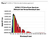
Terrestrial solar irradiance is defined as the amount of electromagnetic energy from our sun arriving at a specific area of the Earth per unit time per unit wavelength. It is often expressed in watts per square meter, per nanometer as in Figure 1.1One may wish to know the total amount of energy, or incident energy, reaching a specific area per unit time. The total incident energy is the integral (the area under the curve) of the terrestrial solar irradiance spectrum. When ASTM G 173-03 is integrated mathematically, the resulting value of approximately 900 watts/square meter is determined. This states that a one square meter surface exposed directly to sunlight with the shown irradiance spectra of Figure 1, will receive 900 watts, or 900 joules of energy/second.
UV energy is 5% of the total incident energy of sunlight. Visible light is 42% of the total incident energy, and near infrared light is 53% of the total incident energy. The time of day, the location and the ambient atmospheric conditions during the solar spectral power distribution measurement will dictate the actual energy breakdown.2 When ultraviolet, visible or near infrared radiation is absorbed, heat is generated. Ultraviolet radiation is also known as ionizing radiation; it has the ability to produce free electrons, and thus free radicals, as well as molecular vibration or heat. Visible light and near infrared radiation, when absorbed, also produce heat energy.3 To reduce the temperature of a substrate exposed to solar terrestrial irradiance, one must maximize total solar reflectance for a given color space.
Total Solar Reflectance
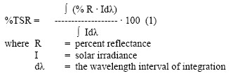
Total solar reflectance (TSR) is a measure of the amount of incident terrestrial solar energy reflected from a given surface. When expressed mathematically, the total solar reflectance is the integral of the percent reflectance times the solar irradiance divided by the integral of the solar irradiance. This equation is integrated over the 280 to 2500 nanometer range:Total solar reflectance can be expressed as a percentage. White coatings exhibit a total solar reflectance of 75% or greater. A white coating, at a total solar reflectance of 75%, by definition will absorb 25% of the incident energy. A black coating, based on carbon black pigmentation, may have a total solar reflectance as low as 3% and, therefore, will absorb 97% of the incident solar energy.
Total solar reflectance can be calculated from reflectance data obtained from a UV-VIS-NIR integrating sphere spectrophotometer. ASTM E 903 outlines a standard test method for determining solar absorptance, reflectance and transmittance of materials using integrating sphere spectrophotometers.4
Total solar reflectance measurements may also be obtained from a Solar Spectral Reflectometer (SSR, Figure 2), such as that available from Devices and Services. ASTM C 1549 utilizes the SSR in determining the solar reflectance of substrates.
Black Body Radiation
Maximizing the benefits of infrared pigmentation technology requires an understanding of emitted radiation. Objects emit radiation as a function of temperature. Maximizing the emissivity of the coating allows more energy to be radiated away from the surface. This results in a cooling benefit. To understand emissivity, one must review the concept of a black and gray body radiator.A black body, by definition, absorbs all incident radiation. A black body will also emit electromagnetic radiation as a function of temperature. Max Planck created a mathematical formula of a black body’s spectral radiant excitance per wavelength as it relates to the temperature of the body. This is Planck’s law of black body radiation.
The spectral radiant excitance per wavelength per meter squared (M2) equals Me:5
Me = (c/4) ueλ (Watts/(M2*M)) (2)
h= Planck’s constant (6.626176 X 10⁻³⁴ J*s)
c = velocity of light (2.99792458 X 10⁸ M*s-1)
k = Boltzmann constant (1.380662 X 10⁻²³ J*K-1)
Where:
ueλ= 8πhcλ-5(e hc/kTλ –
1) -1 (J*m-3) (3)
T= absolute temperature in Kelvins
λ = wavelength in meters
(Note: to convert Me to Watts/(M2*nM), multiply by 1 X 10⁻⁹)
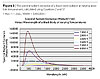
Planck’s law can be demonstrated by heating a metal rod in a fire. As the temperature of the rod increases, the rod will begin to appear red from emitted radiation. When the temperature is further increased, the color of the rod will shift from a dull red to a more energetic (bluer) wavelength. Figure 3 illustrates the spectral radiant excitance of a blackbody at varying absolute temperatures.
The total energy emitted from a black body radiator over all wavelengths at a constant absolute temperature measured in Kelvin is expressed in watts per square meter by the Stefan-Boltzmann Law as:6
Energy Emitted = σ(T4) (4)
Where:
σ = Stefan-Boltzmann Constant
= 5.670 400×10−8 W·m-2·K-4
T = absolute temperature in Kelvin
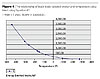
Figure 4 shows the emitted energy/square meter of a black body radiator at temperatures encountered in every day life. As can be seen from the plot, a black body radiator at a temperature of 200 °F emits a significant amount of thermal energy (just over 1000 watts/square meter).
Gray Body Radiation
Perfect black bodies seldom exist in nature. Objects generally deviate from the emittance of a black body in a fractional way, and are called gray bodies. A gray body deviates in emittance from a perfect black body radiator by a defined fraction expressed in terms of emissivity (e< 1 ). It is noteworthy to mention a gray body’s emittance is not wavelength dependent, and is therefore constant. In reality, an object’s emittance is dependent upon both wavelength and angle of observation; the intensity varies with the measured angle and measured wavelength.7The cause of this angle and wavelength variation is related to a material’s conductivity and surface diffusivity and is explained by electromagnetic wave theory.8
Emissivity
The greater the emissivity of a surface, the lower the heat build in the object, when all other variables remain constant. For the formulator, this factor is quite important, as one must maximize emissivity when designing infrared reflecting coatings; the greater the emissivity of an object, the greater the object’s ability to radiate electromagnetic energy. Emissivity is measured with an emissometer. Several different types of emissometers are available. A standard test method for measuring the emittance of surfaces is ASTM E 408. Table 1 shows several emissivities of common objects. Figure 5 is a photograph of a Devices and Services emissometer used for emissivity measurements.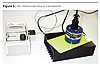
Heat Build Testing
ASTM D 4803 is a test method predicting the heat build-up of exterior objects (objects exposed to the sun) in the laboratory. This test method consists of placing the sample to be tested above a thermocouple in an insulated box. The sample is exposed to a 250 watt heat lamp until thermal equilibrium is achieved. The resulting temperature delta above ambient is used to calculate a predicted heat build correlating to the temperature of an actual exposed exterior surface. ASTM D 4803 was designed for vinyl substrates, but it may be applied to other coated and composite substrates.10Figure 6 is an example of the ASTM D 4803-97 heat build apparatus.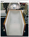
Opacity and Light Scattering
Opacity is defined as the ability of a coating to mask a substrate. Opacity is a function of reflectance, absorption and light scattering. For a pigmented coating, reflectance and light scattering are directly related to the refractive index of the pigment and the medium or polymer surrounding the pigment. The greater the difference in refractive index between the pigment and polymer matrix, the greater is the ability of the film to reflect and scatter light. It is notable to mention that refractive index is wavelength dependent. Light scattering efficiency is also directly related to the relationship of the wavelength of incident light, and the shape and size of the pigment particle.Infrared reflective coatings must be formulated with careful consideration of the substrate. If the substrate is highly absorptive, a formulator must attempt to achieve full opacity in order to prevent light energy transmission through the film to the substrate. When applying infrared reflective pigmentation technology the formulator must recognize that a coating may achieve opacity in the visible region of the electromagnetic spectrum, however, it may be translucent in the near infrared. If full opacity is unobtainable, utilization of a white base coating will improve total solar reflectance. Any light transmitted through the topcoat will be reflected by the base coat, assuming the base coat is, in and of itself, opaque.
Conclusions
Infrared reflective pigmentation technologies can be utilized to minimize heat build in objects exposed to sunlight or other radiant energy sources, resulting in local energy efficiencies and physical performance property enhancements, including a visually appealing color.
The energy efficiencies gained by utilizing infrared reflective products add value to existing products incorporating the new pigmentation technologies. To achieve the greatest infrared reflective benefit and achieve the lowest heat build-up of a surface, formulators must:
- maximize total solar reflectance and emissivity of the surface;
- avoid contamination of infrared reflecting products with highly absorptive products; and
- consider the impact of the entire coating system and substrate to maximize performance.
For more information, contact David M. Hyde, Coatings Process Development Engineer, at dhyde@plasticolors.com; Benjamin Arnold, Market Development Manager, at barnold@plasticolors.com; or Elizabeth Campbell, Product Development Manager, lcampbell@plasticolors.com.
References
1 www.ASTM.org, ASTM G-173-03
2 Holman, J.P. Heat Transfer, 2nd ed.; McGraw-Hill, 1990; pp 471-472.
3 Fessenden, R.J.; Fessenden, J.S. Organic Chemistry, 6th ed.; Brooks/Cole Publishing, 1998; p 892.
4 Parker, D.S.: McIlvaine, J.E.R.; Barkaszi, S.F.; Beal, D.J.; Anello, M.T. Laboratory Testing of the Reflectance Properties of Roofing Materials (2000), FSEC-CR670-00, Florida Solar Energy Center, Cocoa, FL.
5 Wyzsecki, G.; Stiles, W.S. Color Science, Concepts and Methods, Quantitative Data And Formulae, 2nd ed.; John Wiley and Sons, 1982; pp 11-12.
6 Holman, J.P. Heat Transfer, 2nd ed.; McGraw-Hill, 1990; pp 390-393.
7 Holman, J.P. Heat Transfer, 2nd ed.; McGraw-Hill, 1990; pp 390-392.
8 Holman, J.P. Heat Transfer 2nd ed.;McGraw-Hill, 1990; p 401.
9 http://snap.fnal.gov/crshield/crs-mech/emissivity-eoi.html
10 Rabinovitch, E.B.; Quisenberry, J.G.; Summers, J.W. Prediciting Heat Buildup Due to the Sun's Energy, J. of Vinyl Tech., 1983, Vol 5, No. 3.
Report Abusive Comment