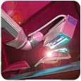
An infrared system cures the base coat paint on truck/SUV bodies.
Ultraviolet (UV) coatings are attractive because of their scratch and mar resistant characteristics, rapid process speed, and environmental friendliness. However, as makers of large and complex three-dimensional parts (such as UV cure composites and automotive refinish primer/surfacers) have looked toward UV, they've found the established techniques of placing fixed lamps end-to-end to be fraught with technical problems and high price tags. Many projects where the coating was developed and proven stalled when the price quotation for a system of 10, 15 or 20 UV lamps was presented.
Solving these problems requires a fresh approach to what equipment is most appropriate and how to best cure these non-traditional parts. Since a 100% UV cure mechanism depends on each facet of the part receiving equal exposure to the UV light source, the challenges of curing something as big and complex as a car body are formidable.

An example of an arrangement of multiple fixed lamps positioned to irradiate a curvilinear part.
Historical Approach
One solution that has been proposed for curing large parts is to use a large number of fixed-position lamps. The lamp positions are pre-set to provide a uniform illumination over the entire part surface. This technique was used in the 2001 Team UV project, which produced a UV-coated racecar.1To achieve the required uniform exposure, a common procedure involves positioning several radiometers on the part's complex surface, making a series of iterative trials, and fine-tuning the position of the lamps after comparing the radiometric data after each trial run.
To reduce the trial-and-error time, methods have recently been proposed that rely on a sophisticated computer simulation to model the exposure of the many fixed position lamps needed to create uniformity.2,3While this approach may expedite the painstaking process of empirically determining lamp position with a radiometer, the model is extremely complex and does not appear to take into account all factors, such as reflections, advance curing as the part moves into the curing tunnel, and other subtle effects that are difficult to model mathematically. Since this approach "imputes" lamp positioning by considering the combined effects of "a thousand points of light," it does not provide much help if the actual measurements do not coincide with the model. The user, faced with the practical problem of what to change, is back to an empirical, iterative solution.

a) The ever-changing geometry of a car body adds to the difficulty of achieving uniform irradiance with fixed lamps due to varying target distance as the part moves past the array.
Limitations and Risks of Fixed Lamp Arrays
The proposal to cure large surfaces using many fixed-position lamps is attractive to the lamp supplier but presents a number of difficulties for the user, including lamp alignment issues, capital cost concerns, and maintenance and statistical process control considerations.Lamp Alignment
Since each fixed lamp has a finite, linear footprint, only a "best fit" can be hoped for on a complex curvilinear surface. As the footprint of the lamp footprint is made smaller, more fixed lamps are required, but a better fit can be achieved. Figure 1 illustrates how an array of fixed lamps can produce relatively uniform irradiation of a curvilinear surface.
While this method is satisfactory for parts where the target distance to the lamp is constant, using fixed lamps is made more difficult by the fact that usually the part is being conveyed through a tunnel of lamps. For example, as shown in Figure 2, the car body does not remain at a fixed target distance to the lamps. And since the entire body must pass before all lamps in the tunnel by conveyor, significant variation can occur.
This means that not only must a "best fit" be developed for any given surface of the body, but that an overall best fit must be achieved for the entire body as it is processed. Assuming such a fit can be achieved for a given part configuration, it will then be necessary to derive an entirely different arrangement for another body style - making setup an enormous undertaking. Some users have expressed concern over how to cure components that face away from the lamps, such as the underside, a difficult top edge or interior surfaces.
Perhaps a simple "gut-check" in considering the idea of fixed lamp curing of a coating is to ask whether it would make sense to apply the coating using a similar arrangement of fixed applicators. In most cases, large and complex parts are coated by hand or with automated guns on reciprocators or paint robots.
Capital Cost
The use of multiple lamps carries a financial burden due to redundancy and inefficiency. Typically, each lamp requires its own power source, cooling apparatus, mounting fixture, controls, etc. One way to mitigate this problem is to use individual lamps with as large a radiant footprint as practical. This approach is only possible with electrode (or arc) lamp technology, since microwave UV lamps are currently restricted to 10 inches or less in footprint. But using larger arc lamps reduces the lamp lifetime and UV uniformity. It also entails larger power supplies and cooling systems, including water-cooled lamp modules.
It appears that a "one (lamp) size fits all" approach is not the best solution for auto bodies. Some surfaces can be treated effectively with large lamp lengths, while others might require smaller sized lamps to accommodate rapidly changing curvatures.
System Maintenance and SPC Considerations
Another undesirable aspect of using a large array of lamps is the challenge of maintaining and monitoring a large number of discrete devices. What is the proper procedure when a single lamp degrades or fails due to aging? If a new lamp is installed on an ad hoc basis each time, then there will eventually be varying intensity levels among the irradiators in the array. By analogy, what should a car owner should do when the first spark plug wears to the point of replacement - replace the entire set, or just the deficient plug?
This raises a further question of whether to individually monitor the output of each lamp module. It is possible for a single lamp to fail and potentially go unnoticed, producing parts that may not have adequate cure. The technology exists to monitor and even closed-loop control lamp modules to maintain consistent output, but the cost of such monitoring and control for very large arrays of lamps may be expensive.
As previously noted, lamp maintenance will necessarily disturb the position of lamps that must be realigned. It has been suggested that the lamps could be mounted on small, motorized micro-positioners, but again the control and capital cost of implementing this technology on large arrays may not be practicable.

b) Using larger lamp lengths improves the cost and logistics of the fixed lamp approach but still presents geometry problems.
Robotic UV Curing
Numerous attempts to use robots to manipulate UV lamps have been attempted for many years with varying levels of success. As pointed out by one lamp supplier, "There are issues that need to be considered when using a robot. First, the lamps must be sufficiently robust to withstand the acceleration and de-acceleration swings of the robot arm, and the lamp must be able to operate efficiently and reliably in a variety of different positions.... Finally, the robot must be programmed to ensure that it delivers the correct UV energy to all parts."4Recent investigations by Daimler-Chrysler into the use of robotic curing for automotive coatings have correctly identified significant challenges related to the process cure window, noting that "if UV technology is to be transferred to the production process of a vehicle painting line, then one should be able to calculate the hardening lines and the movements of the hardening movements. Simulation tools are needed for this purpose."5
In 2004, a group of companies formed the North American Automotive UV Consortium to develop these and other missing tools and techniques to advance robotic UV curing. The group initially developed a "roadmap" to guide the team's development efforts. Initiatives outlined within the roadmap included developing UV sources suitable for robotic use; characterizing the output of these sources (i.e., the radiant "footprint"), developing off-line programming simulation tools for light path programming; developing tools and techniques for online validation of simulations; conducting cure test studies with coating suppliers; and collaborating with car makers on pilot and production scale programs.

Sophisticated ray tracing (a) and modeling (b) of lamps is necessary to achieve uniform irradiance and to simulate UV curing offline.
Developing Robotic UV Sources
Many of the existing UV sources are not ideal for robotic applications because they are too complex, unstable or heavy, or require too many interconnections to be mounted on a fast-moving robot arm.A compact arc lamp source weighing approximately 18 pounds was developed for use on a wide range of industrial robots with capacities in the <10 kg (22 pounds) range, thereby keeping the cost of the robot to a minimum while providing a broad selection of units. The lamp contains few electronic components that are susceptible to damage or variation during rapid acceleration. A shutter is provided both to ensure the safety of the operators and to provide full powder to the part within a few milliseconds of electronic shutter triggering, thus allowing the car body to be in position before beginning exposure to UV energy. The system was also designed with minimal hoses and electrical connections to facilitate mounting the lamp to the robot and keep interconnections from becoming accidentally twisted or entangled during lamp articulation.
A second source consisting of a UV LED array was used for testing. While the UV output of the LED array is somewhat lower than traditional arc lamp sources (maximum of approximately 2W/cm2), UV LED technology is rapidly developing. The advantages of the LED array are its extremely long lifetime (>30,000 lamp hours), the instant on/off capability of the device (2 milliseconds from off to full power), and the lack of direct heat emitted by the array to the target. The output of the array is a narrow bandwidth falling from 385-405 nm. One advantage of robotic manipulation of the UV LED array is that extremely close (~1.0 inch) target distances can be maintained, which provides higher average peak irradiance than could be achieved with fixed positioning of UV LED arrays. The results obtained in lab trials are very encouraging.
Sophisticated ray tracing (a) and modeling (b) of lamps is necessary to achieve uniform irradiance and to simulate UV curing offline.
Characterizing the UV Source
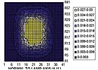
The radiant energy profile of the UV arc lamp source was "mapped" to accurately determine the footprint of the lamp. This footprint allows a UV robot "tool" to be created for the offline simulation software.A model of the lamp output can be described quantitatively in the x, y, and z axes (see Figure 3). Thus, the proper orientation and target distance of the lamp can be used in the robot off-line simulation. Proper rotation of the lamp can also be programmed so that the lamp is kept normal to the tangent of the surface at all times - a capability that is not possible without lamp articulation.

Fine tuning the path over the course of several runs to minimize variation in peak irradiance as measured on 10 different UV sensors.
Developing Off-Line Simulation Tools
An ongoing effort of the consortium is the development of simulation software for off-line light path development and analysis. This software will permit car makers to develop and fine tune curing paths without interrupting production.Modeling the UV lamp tool allows for programming paths with proper overlaps to minimize potential "striping" of the part while achieving maximum uniformity in the fastest production cycle time. The program also includes the ability to track the conveyor in real time, which allows paths that minimize the effects of "mapping" or pre-curing of a coating due to advanced exposure to UV light.
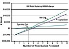
Cost model results for replacing variable power, 600 W/in lamps with a similar output robotic curing cell.
On-Line UV Trials
A number of on-line trials have been conducted at the Fanuc Robotics facility in Toledo, Ohio. The goal of these trials was to evaluate the performance of the UV source and the accuracy of the model, and to evaluate the effects of robot arm speed, conveyor speed, part presentation and other variables.Radiometric data was collected using a novel device called the 3DCURE. The multi-sensor data acquisition unit allowed the consortium to collect UV data from various locations on a complex surface. Sensors were embedded into locations that were predicted to be difficult to cure with fixed lamps.
The robot program was then fine-tuned to achieve uniform peak irradiance on an automotive door panel moving at a line speed of 12 fpm. Once uniform peak irradiance was established, robot variables were tuned to achieve equal UV dose. Power output of the lamp was kept constant for all testing. The unit is capable of producing 500 W/in at full power.
Another advantage of the robotic technique is that the target distance to the part can be set - and maintained - at the optimum distance for the reflector design. For many lamp units, especially those using elliptical reflectors designed to focus to a line, the focal lengths are relatively close (typically around 2 inches from the face of the lamp). This means that the lamp must be operated out-of-focus (in what some refer to as the "far field"). While this is a common practice, it is also inefficient as the power falls off rapidly in the far field.
Figure 4 shows the process of fine tuning the light path for consistent peak irradiance during one of the earliest line trials. The total time to tune the system so that peak irradiance is kept within a narrow range is estimated to be less than one hour.
Preliminary Results
Of the six steps outlined in the roadmap developed by the consortium, solid progress with encouraging results has been obtained from efforts on the first four:- The UV lamp designed for robotic use is a successful development. The unit is lightweight and agile, and therefore poses no obvious problems in use. The shutter system was an important safety feature for frequent trials.
- Several improvements will be implemented in the next generation of lamp design. Several ideas were also presented for improvement in how to integrate the lamp unit to the robot.
- Off-line programming work is under way and is already yielding positive results. Lab trials identified many features that can be added to the programming.
- On-line data collection using the 3DCURE unit was successful in allowing the team to rapidly develop paths that yielded uniform peak irradiance and energy density. Several improvements to the data collection system are being implemented to make higher speed data collection easier.
- The radiometric data indicates that a sufficient peak irradiance and dose can be achieved with the line speed (12 fpm) and robot arm speed (600 mm/sec) that were used during the trials to effect proper cure of commercial formulations (based on baseline cure data provided by coating formulators). This result opens the doors to steps 5 and 6 of the roadmap, which will involve the curing of coatings at production cycle times.
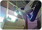
In the robotic curing of large 3-D parts, the robot can easily track a moving part to optimize cure and cycle time.
Cost Model Development
The North American Automotive UV Consortium has developed an interactive cost model that provides comparative capital and operating cost data needed by manufacturers. A summary of cost model results for replacing variable power, 600 W/in lamps with a similar output robotic curing cell is shown in Figure 5.The results presented here are for a simplified model in which capital cost is based on list costs of all equipment under study, published energy consumption and replacement parts costs. The model doesn't attempt to quantify "soft costs" involved in equipment setup times, floor space consumption, downtime, etc., which appear to favor a robotic approach. The capital cost comparison is sensitive to the cost of the robot, since this is a relatively expensive component. The comparison anticipates a $60K robot and associated hardware needed for integration. The model is also sensitive to the cost of fixed lamps. The comparison was computed using microwave-powered 10-inch lamps rated at 600 W/in with variable power supplies, since the literature suggests that variable power may be necessary to achieve the required uniformity and to provide various monitoring features.
While numerous scenarios have been evaluated, a few trends are already clear. First, the operating cost of a single robot lamp is always less expensive than a multi-lamp array. The lower cost is due to the lower parts replacement requirements and the lower energy consumption of a single robot lamp.
Second, the capital cost of eliminating fixed lamps with a robotic cure system is higher until a threshold number of fixed lamps are replaced. In the model presented in Figure 5, the robotic system has a lower capital cost once an array of five of more fixed lamps is replaced. If more exotic equipment is anticipated (such as lamp monitoring, or micro- positioners for fixed lamps), then the robotic system may offer capital savings compared to even smaller arrays. Conversely, the use of exotic robotic equipment may make the robotic system more costly to install.
Future Development
While good progress has been made leading to several improvements in the tools and technology for robotic UV curing, there is a still a steep development curve to be tackled. Continued refinement of the robotic UV lamp sources is needed, including UV LED and dual-head lamp development for improved robustness, lower cost and more flexibility. Improvements in the off-line simulation software are also needed to incorporate new variables observed in on-line trials so that off-line simulation and real world cure experience are related as closely as possible.Improved data acquisition tools will allow the consortium to more accurately program and measure UV irradiation to further define the process window. For example, UV Robotics has applied for a patent on a method of measuring the uniformity of UV irradiation using a real-time, infrared thermographic imaging camera, which permits visualization of UV irradiation by measuring the effects of waste-heat emitted along with UV from the lamp.
Refinements to the first four steps of the roadmap will lead to future expansion of the testing to include actual curing of coated parts under simulated production conditions (such as cycle time). This work has already begun on a range of plastic parts, wheels and other components. The group anticipates expanding its membership to include coating suppliers and tier-one and OEM automotive partners.
Potential Applications
While the goal of the consortium is to provide car makers with a set of tools that enable the use of UV coatings, the work also has implications for tier-one producers and other industrial processes.In one example, a single robotic lamp was able to cure a clear coating on an automotive headlight lens that is currently cured using 12 fixed position microwave lamps. The UV energy required for the task was significantly reduced, from nearly 7.0 Joules to 2.5 Joules. This dramatic efficiency is possible since the light is used more efficiently.
In another popular application, a new physical vapor deposition (PVD) metallization system for alloy wheels requires that UV be cured in the difficult recesses of the wheel. The UV Robotics lab plans to include a PVD chamber that will allow customers to develop an entire coating, metallization and curing process.
The ornate cutouts popular with high-end customers are difficult to cure with fixed lamps since many shadow problem areas exist. The robotic UV approach solves this problem nicely.
As UV coatings continue to find their place alongside traditional coatings for a wider array of parts, the need for economical curing systems will become more prevalent. Robotic UV curing makes sense both from a technical and an economic standpoint and is likely to grow in popularity, especially for those with larger and more complex parts that cannot justify large, fixed lamp designs.
Author's Acknowledgements
This article is based on the work of UV Robotics and a consortium of talented and dedicated specialists. I wish to acknowledge the contributions of the following companies and individuals: Oliver Treichel and Oliver Starzmann of IST Metz GmbH; Dennis Kaminski of IST America; Mark Owen, Tom Molamphy, Jon Marson and Alex Schreiner of Phoseon Technology; Keith Torp, Jerry Perez and Ed Walczak of Fanuc Robotics, North America; David Snyder and Kyle Bostian of EIT Instrument Markets; and Paul Gorgias, John McDonough and Renny Wolfson of UV Robotics LLC.For information on reprints of this article, contact Jill DeVries atdevriesj@bnpmedia.com.
Report Abusive Comment