
The Clean Air Act of 1992 (Phase I) and 2000 (Phase II) aimed to reduce annual sulfur dioxide (SO2) emissions by 10 million tons between 1980 and 2010 (almost half the 1980 level). In March 2005, the Clean Air Mercury Rule was enacted to reduce mercury emissions in two phases. Phase I will decrease emissions from 48 tons to 31 tons beginning in 2010, while Phase II will continue the decline to a cap of 15 tons when the program is fully implemented. Also in 2005, the Clean Air Interstate Regulations (CAIR) went into effect to reduce emissions of nitrogen oxides (NOx) and sulfur dioxide (SO2). These regulations affect all industries, including chemical, petroleum and power plants, in an effort to reduce the amount of toxic pollutants (in the form of SO2, NOx and CO) being released into the atmosphere. By 2012, all power plants will be required to meet the tougher air quality emission standards.
Adding flue gas desulfurization units (FGDs) to clean or “scrub” the exhaust gases can reduce SO2emissions by as much as 98%. As a result, more than 300 FGD systems are expected to be built in the U.S. by the year 2010. However, the environment in which these systems operate is extremely harsh. With each FGD unit costing several hundred million dollars, use of the right linings and coatings, as well as high-quality application processes, is crucial to optimizing a plant’s investment.
Wet Systems and Corrosion
There are basically two types of FGD systems - dry and wet. Dry systems use the heat of the incoming flue gas to vaporize the liquid in the lime slurry, which is used to scrub the sulfur dioxides from the gas, resulting in a dry waste stream. These units usually are reserved for plants burning low-sulfur coal, as their performance with high-sulfur coal has not been fully demonstrated.“Wet” scrubbers use an excess of slurry and produce a wet waste stream. All internal surfaces are subjected to a saturated environment or are in immersion. Due to their higher removal efficiency, wet systems dominate the FGD market, comprising 75-80% of all scrubbers used. Modern systems are smaller and more reliable than their predecessors. While older designs relied on numerous absorber units per boiler, today’s absorbers are being designed with one vessel to service one or more boilers, which makes them more efficient.
The purpose of a wet FGD system is to remove sulfur dioxide from the flue gas by creating a chemical reaction with a lime or limestone slurry to form calcium sulfate (gypsum). This process results in an environment that is highly corrosive to carbon steel and most common stainless steels. The internal components of the scrubber are either submerged or are in contact with a warm saturated gas, and the process of combining a gas containing sulfur dioxide with a wet environment produces sulfuric acid. Further, the chloride content of the fuel, combined with the action of recycling the process water, results in elevated chloride concentrations. Other corrosives such as nitric acid and fluorides might be introduced to the system at low levels through coal combustion or water quality. The process operates at elevated temperatures, with inlet temperatures ranging from 280 to 350°F and post-quench-area temperatures between 120 and 140°F. Because of the corrosiveness of the environment, the choices for the materials of construction are limited and are influenced by cost and availability.
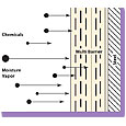
Figure 1. Adding glass flakes to a vinyl ester resin lining system creates a tortuous path for the water molecule, which increases the lining’s resistance to water penetration.
Customization Options for Interior Linings
Various options are used to protect the interior of the FGD absorber vessels and auxiliary tanks. Some of the highest-performance linings are based on vinyl ester resins. These resins offer excellent properties for a lining system by themselves, but their performance is greatly enhanced by a mixture of additives, including glass flakes, powdered ceramics, mats and rovings, and paraffin. Using additives allows the lining system to be tailored to a number of distinctly different sets of performance characteristics. Such customization is crucial for FGD applications, which present a number of drastically different application zones.Glass Flakes.Adding glass flakes improves the product permeation rate or resistance to water penetration. All lining systems are permeable to some extent; however, glass is less permeable than vinyl ester. A layer of vinyl ester resin offers a theoretical pathway equal to the thickness of the lining - for example, a 40-mil-thick coat of vinyl ester resin provides a theoretical path of 40 mils in length for a water molecule to reach the substrate. In a vinyl ester flake glass system, when a water molecule begins to permeate the vinyl ester resin it will encounter a glass flake. Since the glass is less permeable than the surrounding vinyl ester resin, the water molecule will not try to permeate the glass, but will take the path of least resistance and travel along the surface of the glass flake or away from the glass flake. Adding the glass flake therefore creates a tortuous path for the water molecule, which increases the theoretical pathway length by magnitudes (see Figure 1).
The permeation performance of a glass-flake-filled vinyl ester is a function of the performance of the glass flakes. Several factors affect this performance, including the flake size and shape, and the adhesion of the vinyl ester resin to the surface of the flakes. Glass flakes typically are added in a ratio of sizes to provide better stacking and overlapping. Glass flakes should be flat to provide better orientation and overlapping characteristics, and a larger average glass flake size is preferable. The adhesion strength between vinyl ester resin and untreated glass flakes is relatively low. As a result, the glass flake needs to be treated with a surfactant, usually silanes, to improve adhesion.
Powdered Ceramics. Vinyl ester resin does not provide enough abrasion resistance to handle the high-solids slurries used in FGDs. To improve the abrasion resistance of the lining, the resin is mixed with powdered ceramics at high loading ratios of three to four parts powder to one part resin. As the resin wears away in an abrasive environment, it exposes the small ceramic beads until the surface exposed to abrasion consists almost exclusively of ceramics. The vinyl ester resin in this example serves only as a binder to hold the ceramics. With the proper mixture of ceramic powders and resin, it is possible to achieve tough linings that not only hold up to slurry flow and impingement, but also to the mechanical wear and tear to which FGD systems are subjected for scale removal during outages. The abrasion control mortars can hold up to water pressures in the 2,500 to 3,000 psi range and, when used as a flooring material, can withstand the bobcats and shovels typically employed for cleaning.
Mats and Rovings. Glass mats and rovings (woven glass cloth) can be embedded in the resin system to provide additional physical properties. They usually are measured in weight per square foot, as in a 1.5-oz chopped glass mat or a 24-oz roving.
Rovings are embedded between layers of trowel-applied abrasion control mortars to provide physical strength, similar to the rebar used in concrete systems. Mats are much lighter and thinner than the rovings and are used to provide reinforcement for physical strength and improved abrasion resistance. It is common to see multiple layers of mats specified, and these often are used with a surfacing veil. Mats also typically are specified for edges in corners to help overcome the effects of surface tension, which causes a liquid to back away from sharp edges. By using a mat, the fibers of the mat hold the resin in place to ensure the proper thickness across the corner. While this is a recommended practice, it should not take the place of proper steel preparation, which requires that all corners be prepared to a minimum ⅛-in. radius.
Paraffin. Paraffin or wax is added to the topcoat or gelcoat to “seal” the system. Oxygen in the air will inhibit and interfere with the vinyl ester polymerization reaction. Sealing the system with a final paraffin coat allows the system to reach 100% cure. Using a topcoat with paraffin also allows the manufacturer to formulate the build coats with longer recoat windows but a relatively short, 72-hour final cure schedule (depending on the ambient temperatures during cure).
Other Lining Systems. Other lining options include fiberglass reinforced plastic (FRP) on epoxy vinyl ester resin; acid-resistant ceramic-based tile; sheet rubber linings based on compounds such as bromobutyl or chlorobutyl; and “exotic metal” linings, which usually are stainless steel modified with high-nickel bearing alloys or high chromium and molybdenum alloys. However, vinyl esters offer the lowest available life cycle cost compared to all of these systems, as well as a comparatively low initial cost. They have a short lead time, shorter installation schedules, more adaptability for modifications, and greater flexibility and adhesion. They possess excellent resistance to inorganic acids, resistance to chlorides well over 1,000 ppm, good resistance to alkali environments, and temperature resistance that ranges from 190°F in wet environments and 300°F in dry environments for standard bisphenol vinyl ester-based flake glass resin systems, to 260°F in wet environments and 390°F for dry environments for novolac-based flake glass resin systems. The thickness and localized designs of vinyl ester resins can provide the right materials for each zone in the absorber so that plants don’t have to overspend for more robust materials where such materials are not required. With the proper design and application, vinyl ester resins are a proven technology that can provide long-term performance.
It is important to note, however, that application is key. Fire safety procedures must be followed, and skilled labor is needed to ensure the proper mixing of components and adherence to temperature guidelines. Detailed engineering is required to ensure that the proper additives are used in high wear and impact areas. Contaminants during installation (water, dust, etc.) can interfere with curing. Vinyl ester resin systems also are susceptible to mechanical damage and therefore require regular inspections and maintenance. Ultimately, the reliability of the lining and the required maintenance costs will depend on the system chosen and on the initial installation methods.
Exterior Coating Systems
Traditionally, three-coat systems consisting of zinc, epoxy and urethane have been specified for FGD exteriors. Zinc coatings are used to provide long-term cathodic protection; however, they have a limited pH range. Epoxy and urethane coatings are required to protect the zinc from atmosphere contaminants.Recent advances in zinc and urethane technologies have enabled faster production schedules in fabrication shops by eliminating the intermediate epoxy coat on some projects. For example, rapid-recoat reinforced inorganic zincs can be topcoated within one to two hours, and a high-build, quick-cure polyaspartic polyurethane technology allows the fabricator or field applicator to apply up to 9 mils in a single coat. The steel usually can be handled within 8 hours instead of 24 hours, which enables fabrication shops to improve their throughput dramatically without sacrificing coating system performance. While a three-coat zinc/epoxy/urethane systems with a total dry-film thickness of between 12-15 mils is expected to perform for 25 years or more, the service life of inorganic zinc/polyaspartic polyurethane two-coat systems is a competitive 20 years or better.
The savings in labor and application/production time obtained from using a reinforced inorganic zinc/polyaspartic polyurethane two-coat 10 mil system versus the traditional inorganic zinc/epoxy/urethane three-coat system can be substantial.

A vinyl ester resin lining is applied in a smoke stack. Photo courtesy ISG - Universal/Blastco.
A Protected System
The three key ingredients for a successful FGD lining and coatings project are a sound system design, an accurate coatings specification, and a high-quality application/installation.Suppliers of coatings and linings should be consulted early in the design phase to recommend the proper systems based on the FGD design and the owner’s project and long-term maintenance objectives. Coatings and linings are an essential part of the FGD system, since they protect this most valuable asset.
Additionally, careful planning is needed to ensure that the products specified will meet the system’s designed life and overall cost of the project, including future routine maintenance. Reducing initial lining or coating costs might be detrimental to the long-term performance of the lining and coating system. Using a single source of supply that offers color and design services, coatings specification development, product training, on-site support, lab technical support and warranty protection can reduce administrative costs and eliminate problems due to incompatible lining and coating systems.
Finally, it is a good idea to have the coating and lining manufacturer involved with training and monitoring of the application. The manufacturer can work closely with the applicator and project inspectors to ensure that the systems meet the requirements. This is especially true in critical areas that are subject to excessive heat, wear or chemical attack.
Following these guidelines can help plants ensure that their FGD systems provide long-term performance of 20 years or more with minimal maintenance costs.
For more information, visit www.futuracoatings.com.
SIDEBAR: Linings and Coatings: A True Cost Comparison
An FGD system and its auxiliary components operate under a wide range of parameters, all of which must be evaluated to tailor the lining system to the required process conditions. A one-size-fits-all approach is a recipe for disaster. At a minimum, the following parameters should be considered: chemical exposure, temperature, immersion, direct impingement, sliding abrasion, substrate, off-line or outage conditions, and desired service life.In reviewing the various types of lining systems and exterior protective coatings, potential owners of new FGD systems should consider both the initial installation costs and the maintenance/replacement costs, along with the available warranty options.
The initial cost to line the various interior and coat the exterior components of an FGD unit can vary greatly. Each lining system has unique qualities that might make it best for a particular service. However, “lower-cost” systems can require more maintenance, which will increase labor and maintenance costs over time.
Warranties can vary from as little as one year to ten years or more. Owners need to understand what is and is not covered by the warranty, including factors such as wear or abrasion, higher chloride levels, higher operating temperatures, chemical attack, and mechanical damage. The obvious goal is to avoid any unscheduled downtime due to a lining or coating failure. Potential weak spots that invite early failure include sharp edges, openings, corners and severe impingement areas. Proper surface preparation and lining design for these vulnerable areas is essential. A material failure that causes a unit shutdown could easily cost a power generation facility $1 million per day in lost operating revenue. It would be adding insult to injury to learn that the warranty has either expired or offers little assistance in repairing the damage.
Reviewing the total system and life cycle costs up front can help plant owners maximize both their equipment budget and operating efficiency.


Report Abusive Comment