


The cost of corrosion is estimated to be at least $276 billion per year in the United States alone.1 A 2001 study commissioned by the Federal Highway Administration analyzed 26 industrial sectors and found that direct costs accounted for approximately 3.2% of the U.S. economy. Often overlooked in these numbers are the costs related to equipment downtime. Time spent replacing or rehabilitating corroded equipment not only ties up valuable manpower, but also makes it necessary to maintain a reserve of excess capital equipment. With some service rotations as short as six months,2 even a modest increase in service life can lead to significant savings.
The most common approach to prevent corrosion is to paint the surface with a protective coating. Most paints have only limited ability to resist abrasion. Attempts to improve durability are ultimately constrained by the requirements that the coating be relatively thin (< 100 µm) and easy to apply. While repainting and touch-up can be performed as part of regular maintenance, many defects go unnoticed before significant damage occurs. Given that coating damage is inevitable, improvements in flaw tolerance may provide greater gains in corrosion protection than incrementally improved flaw resistance. To this end, we present self-healing coatings that autonomously repair scratches below a maximum width, delaying the onset of corrosion and increasing the time between maintenance cycles.
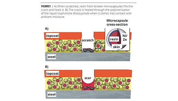
Self-healing is achieved through a powder additive that consists of metal microcapsules with a Ni:Zn alloy shell and a diisocyanate monomer resin interior. The microcapsules can be tailored for any primer system, but for the purposes of this study, the diisocyanate monomer has been chosen for compatibility with single-component polyurethane primers. The mechanism by which the microcapsules heal the coating is illustrated in Figure 1. When scratched, the resin flows to the damage zone and cures upon exposure to ambient humidity to repair the coating. The percolating network of Ni:Zn spheres is sacrificed anodically in lieu of the steel substrate if healing is incomplete.
Experimental
Reagents
The following reagents were purchased from Sigma Aldrich and used without further purification unless otherwise noted: isophorone diisocyanate; poly[(phenyl isocyanate)-co-formaldehyde], Mn ~400; poly(ethylenimine) 50% (aq), Mn ~60 000; poly(acrylic acid) 35% (aq) (Mw ~100000); gum Arabic; nickel(II) sulfate hexahydrate; zinc(II) sulfate heptahydrate; sodium hypophosphite; DL-lactic acid; DL-malic acid; Tergitol NP-9; sodium acetate; ammonia 4.6N (aq); diethylenetriamine; tin(II) chloride; palladium(II) chloride; hydrochloric acid; and MIL-P-26915 (proprietary polyurethane primer from NCP Coatings).
Microcapsule Synthesis
Oil-in-water emulsification accompanied by interfacial polymerization produced spherical microcapsules with a liquid interior and thin polymer shell. An IKA overhead stirrer (Model # 2600001) vortexed the solution. The oil phase was prepared from a mixture of isocyanate-functional monomers, which included: poly[(phenyl isocyanate)-co-formaldehyde] (PPI), isophorone diisocyanate (IPDI), toluene diisocyanate (TDI), and purified MIL-P-26915 urethane resin. The aqueous phase consisted of a 5% (w/v) aqueous gum arabic solution. To 20 g of this solution was added a mixture of water-soluble crosslinkers, which included 5% (w/v) diethylenetriamine (DETA) and 5% (w/v) polyethylenimine (PEI). 20 g of monomer mixture followed by 20 g of crosslinker solution were then placed into 75 mL of a 5% (w/v) aqueous gum arabic solution and stirred to 2000 rpm using the IKA stirrer. The solution was allowed to stir for up to 3 h and then allowed to react for up to 4 days at 23 °C. The supernatant was decanted and the microcapsules were washed three times with MilliQ water. Typical reactions yielded 20 g of microcapsules.
Microcapsule Size Analysis
Size analysis experiments were conducted by varying the spin speed of the IKA overhead stirrer from 500-2000 rpm during the interfacial polymerization reaction. An IKA double-bladed R 1355 centrifugal stirrer (IKA model # 1132700) was used to produce the microcapsules. All images were obtained with an Olympus optical microscope (model # BX60MF5) and a Leica DFC306 FX digital camera. Quantitative image analysis of the sphere size distribution was performed using ImageJ software.
Electroless Deposition
Microcapsules (20 g) were washed once with 100 mL of a 100 mM PBS buffer pH 7.4, and then placed into 100 mL of a 2% (w/v) poly(acrylic acid) solution (aq) in 100 mM PBS buffer pH 7.4 and allowed to stir for 10 min. These microcapsules were decanted and washed with MilliQ water. The microcapsules were then placed into 100 mL of an acidic SnCl2 solution (10 g/L SnCl2 and 5 mL/L HCl) and allowed to stir for 10 min. After washing again, microcapsules were then immersed in an acidic PdCl2 (aq) solution (0.5 g/L PdCl2 and 4 mL/L HCl) for 2 min. These microcapsules were then decanted and washed, and then placed into an electroless plating solution containing 22.4 g/L nickel sulfate hexahydrate, 8.2 g/L zinc(II) sulfate heptahydrate, 100 g/L sodium hypophosphite, 21 mL/L DL-lactic acid, 4 g/L DL-malic acid, 1 mg/L Tergitol NP-9, and 8.5 g/L sodium acetate. Aqueous ammonia (4.6 N) was used to adjust the plating solution’s pH to ~4.7-4.8. The solution was heated to 60 °C using a Corning hot plate (model # PC-400D) and allowed to plate for 2 h. After plating, the microcapsules were filtered and washed with MilliQ water. Lastly, the microcapsules were lyophilized to remove any residual water.
Metal Thickness Measurements
Metal thickness of the spheres was determined through SEM images of the cross-sectioned microcapsules. Microcapsules were immobilized into a cured epoxy resin and mircrotomed to reveal their cross-sections. The microtomed samples were imaged via a Hitachi SEM model S4700.
Metal Shell Composition
Chemical compositions of metal coatings were analyzed using inductively coupled plasma atomic emission spectroscopy (ICP-AES). Samples were prepared by first immersing in 10 mL of trace metal grade HNO3 (70% wt), followed by microwave digestion. The measurements were conducted by a Varian Vista Pro Axial ICP-OES with a plasma flow of 15.0 L/min, an auxiliary flow of 1.50 L/min, and a nebulizer flow of 1.05 L/min.
Experimental Primer
Test primers were made by mixing 25% (w/w) lyophilized capsules in MIL-P-26915 commercial polyurethane. Four grams of primer were gravity fed across low-carbon steel panels (Q-Panel type S-36) to produce a consistent, uniform film thickness of 175 µm (+ 50 µm, - 25 µm), measured in a minimum of six locations using ball-tipped micrometers. The microcapsule concentration was chosen so that the dried film contained approximately 55% (v/v) microcapsules, which is the critical pigment volume concentration (CPVC) for this system.
Coating Testing and Evaluation
Ground finish cold rolled steel panels (ASTM A1008) 3 x 6 x 0.032 in. were coated with paints for mechanical testing. As a control (CARC control), one set of panels was spray painted with a 25 µm-thick coating of MIL-P-53022B epoxy-polyamide primer followed by a 50 µm-thick coating of MIL-DTL-54159 polyurethane topcoat. A second control (zinc control) was made by painting a 75 µm coating of MIL-P-26915 zinc-rich primer, followed by 25 µm of MIL-P-53022B and 50 µm of MIL-DTL-54159. As described above, the experimental coatings consisted of a single, 175 µm (+ 50 µm, - 25 µm)-thick layer.
Adhesion was measured using the ASTM D3359 Method A Tape Test. The coated test panels were then scribed to produce scratches of increasing width using the following five tools: razor blade, scratch awl, 1/64 in., 1/32 in. round, and 1/8 in. lathe tools. Panel backs were spray painted with Rustoleum to prevent unwanted corrosion and contamination. Per MIL-P-26915 specification and with guidance from ASTM D870 and D1308, scratches were permitted to cure for 10 days and then individually immersed in separate 1000 mL beakers filled with ~850 mL of DI water at 38 °C for 24 h. Upon removal, the panels were rinsed with water, blotted dry and inspected for change in appearance (blistering, cracking, etc.). The level of corrosion in each scratch was graded on a 0-4 scale, where 0 represents 100% rust and 4 represents no rust. The adhesion tape test (D3359) was repeated on the section of the panel that was immersed within one hour of removal. Each test panel was photographed pre- and post-evaluation to document its condition.
Results and Discussion
Microcapsule Size
The first step of microcapsule synthesis is the emulsification of an oily mixture of isocyanate monomers in water.11 By holding the reagent concentrations and temperature constant, the size of the microcapsules could be controlled by changing the spin speed of the overhead stirrer. The stirring rate was varied from 500 to 2000 rpm to determine the relationship with particle size distribution.
Paints are engineered to have precise viscosity and surface tension under the shear rates experienced during application. The viscosity in particular is a strong function of particle size and size distribution.3-7 In general, smaller particles result in a greater viscosity for the same mass loading, but larger particles clog spray equipment. The particle size must also be small relative to the coating thickness (~75 - 100 µm) to ensure a smooth film. With respect to the healing capacity of the final coating, Rule, et al.8 found that the amount of liquid delivered to the crack face is directly proportional to the microcapsule diameter. Ideally, the microcapsules should therefore be as large as possible without exceeding the diameter of the spray nozzle or the thickness of the final film. These considerations dictate a practical upper limit of about 50 µm. A stir rate of 2000 rpm yielded an average diameter of 36 ± 17 µm, which was used for all microcapsule synthesis in this study.
Polymer Skin Thickness
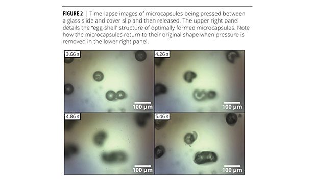
The second step of microencapsulation is to form a solid polymer skin around the oily droplets through an interfacial polymerization. Though they react with water, isocyanates more readily polymerize with amine-functionalized crosslinkers that can be added to the aqueous phase.9 Pilot experiments showed that thin, rubbery polymer skin layers did not have sufficient barrier properties to protect the resin interior during subsequent plating steps. A thicker, glassy polymer skin layer was required for protection. It could be readily identified by the brittle fracture mechanism displayed when the microcapsules were pressed between a glass slide and coverslip. This behavior was used as a quick method to determine whether the microcapsules could withstand electroless plating (Figure 2).
Electroless Deposition
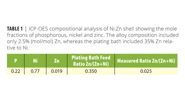
Electroless plating occured for 180 min (Figure 3). Measured by SEM cross-sectional analysis of the microcapsules, the thickness metallic layer was approximately 1.4 µm thick after 1 h of plating. The chemical composition of the metal shells was determined via ICP-OES (Table 1). Despite using 35% (mol/mol) Zn in the plating bath, the actual composition of the metal deposit included only 2.5% Zn relative to nickel. Also included was 22% phosphorous (P). Although phosphorous is not primarily responsible for providing galvanic protection, its concentration has a number of important consequences. Concentrations above 9% (mol/mol) are believed to favor amorphous over FCC Ni deposits.10 Higher P content may also provide beneficial catalytic effects, in addition to decreasing the built-in stress that causes exfoliation and corrosion in high-pH, low-phosphorous films.11
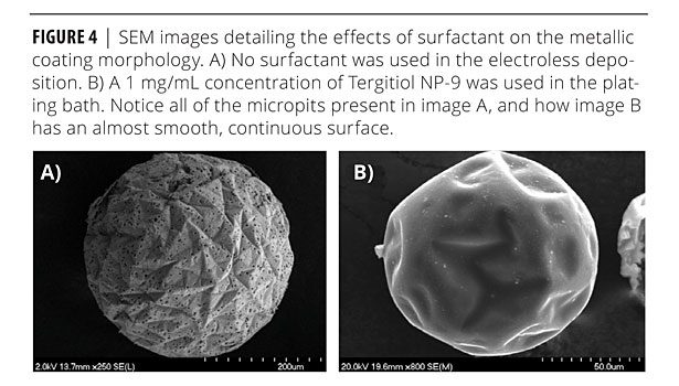
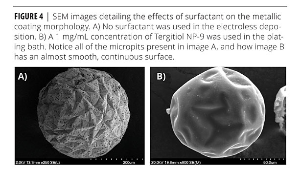
Preliminary metallic coatings showed many pinhole-like structures in the coatings (Figure 4). Chen et al.12 had discovered that these structures occur due to the nucleation of hydrogen onto the surface of the Ni-P coating during the catalytic breakdown of the hydrogen phosphate. In order to eliminate these micropits, Chen introduced a surfactant to the plating bath. The surfactant molecule removed the hydrogen bubbles from the surface of the substrate through adsorption at the H2-liquid interface. The effectiveness at reducing micropitting is governed by the surfactant’s structure and dosage in the plating bath. A 1 mg/mL concentration of Tergitol NP-9 was the most effective at reducing micropitting in the electroless deposition reaction followed in this research. Reduction of the micropitting is important in producing a metallic coating that adheres strongly to the microcapsule and does not suffer from delamination.
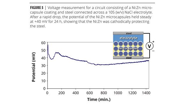
The metallic layer of the microcapsules served a dual functionality. Not only did it provide the capsule with much needed mechanical stability, but it also served as a sacrificial anode. The addition of Zn to the nickel alloy increased the electrochemical potential difference with respect to steel.13 The Ni:Zn alloy had a corrosion potential of -0.337 versus a saturated calomel electrode (SCE).16 Cathodic protection was demonstrated by a simple experiment in which a steel nail coated with a Ni:Zn microcapsule-filled primer was connected electrically to an uncoated nail (Figure 5). The two nails were then placed in a 10% w/v NaCl aqueous solution to complete the circuit. Under these conditions, the Ni:Zn coating initially exhibited a +183 mV potential with respect to the uncoated nail. This potential eventually dropped to approximately +40 mV, where it remained for the subsequent 24 h of immersion.
Primer Formulation
The zinc filler in MIL-P-26915 primer was removed by centrifuging at 10,000 g for 30 min, leaving behind the pure resin. To this resin was added 25% microcapsule filler by weight. This concentration was the maximum for which a smooth, dense film could be produced. Higher weight fractions resulted in rough surfaces and interior voids. The transition from a dense film to voiding occurs at a volume fraction known in the coatings industry as the critical pigment volume concentration (CPVC).14-16 Typically between 55-60 vol%, it frequently represents the optimum loading of filler and pigment since many of the beneficial properties of the additives are maximized at this loading. In the current system, the CPVC defines the maximum healing capacity.
Primer Panel Test and Evaluation
The ASTM D3359 Method A Tape Test scores were comparable (all passing) for both the control and experimental panels in the dry state. The 24-h immersion in DI water at 38 °C did not generally affect the experimental panels, but the CARC control failed examination after experiencing a 30% decrease in adhesion score. The absence of adhesive or cohesive failure for the experimental primers indicates excellent interfacial adhesion between the Ni:Zn microcapsules and the purified MIL-P-26915 resin.
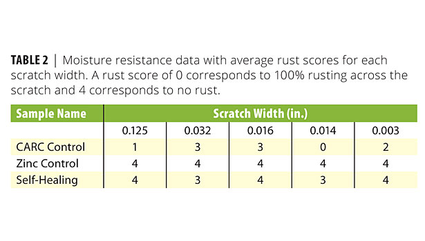
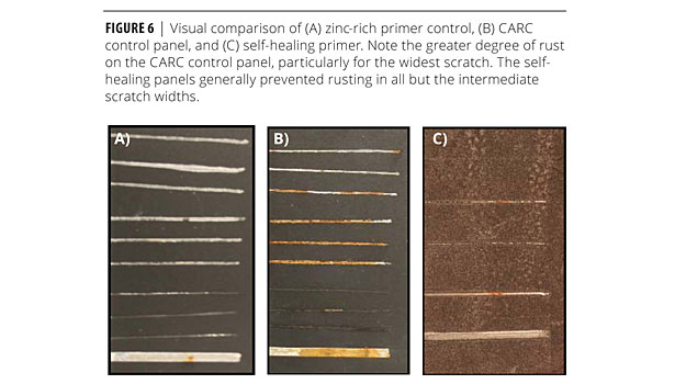
The moisture resistance test showed great improvement relative to the CARC control panel (no zinc). Table 2 shows that most scratches on the CARC control experienced between 25% and 100% rusting, whereas the self-healing panel only permitted a small amount of rust on the 0.032- and 0.016-in. scratches. The CARC coating system with the zinc-rich primer did, however, perform the best overall with no rust present in any scratch. Figure 6 shows a side-by-side visual comparison of the self-healing coating and the CARC control.
The major result from the moisture resistance test was to show that the metallic microcapsules successfully healed both the thinnest and thickest scratches. While only a small amount of rust was present for intermediate scratches, its presence indicates both that healing was incomplete and that the galvanic protection provided by the Ni:Zn shell was insufficient under these conditions. The dependence on scratch width can be explained by noting that small scratches only require a small volume of resin for self-repair. In contrast, the wider 0.014-, 0.016-, and 0.032-in. tools cut deeply into the steel panel. Optical microscopy revealed porous damage zones on either side of the scratch. Upon further visual inspection, the majority of the released resin absorbed into this debris rather than spreading upon the exposed steel.
Such behavior would be expected, given that the interfacial tension between the polymer and uncured resin is lower than that between the resin and steel. The surprising result, then, was that the widest scratch (0.125 in.) was able to heal. Visual inspection under a light microscope showed that the wide but blunt scraping tool released large volumes of liquid. Although the 0.125-in. lathe tool removed a large volume of material, the amount of released resin was apparently large enough to compensate for the total scratch width. This result suggests that the scratch width alone is insufficient for predicting whether the self-healing mechanism will fail. Other factors such as scratch depth and the extent of coating damage in the adjacent areas must be taken into account.
Although thicker metal shells would increase the capacity of the sacrificial anode, the fact that Zn-rich primers outperformed the self-healing primers calls into question the amount of galvanic protection that the Ni:Zn shell provides. The ability of the experimental coatings in their current form to prevent corrosion therefore appears to depend more strongly on the self-healing capacity of the stored resin. That said, a number of experimental primers demonstrated broad protection against corrosion for all scratch sizes. The Ni:Zn microcapsules may therefore be providing galvanic protection, albeit not to the level of the Zn-rich primer. Efforts are currently underway to improve the galvanic protection capacity through improved shell thickness, further optimization of the alloy composition, and improved electrical contact between the steel substrate and percolated network of metallic microcapsules.
Conclusions
Metal-coated polyurea microcapsules with an encapsulated water-reactive monomer, IPDI, were successfully synthesized. Stirring rate controlled the average diameter, and hard, glassy polymer skin layers were required to protect the encapsulated diisocyanate resin from premature curing. The metallic coating was converted into a sacrificial anode by incorporating zinc into a nickel electroless plating procedure.
Experimental primer coatings were successfully made through the incorporation of metal microcapsules into a commercial polyurethane primer. The experimental primer was evaluated through various ASTM measurements. Through these evaluations, corrosion resistance and self-healing capacity were successfully demonstrated. Though the tests did not reveal conclusive evidence of galvanic protection, they did reveal improved corrosion protection relative to conventional coating systems with particular note that both narrow scratches and wide scratches could be successfully repaired.
Acknowledgements
This research was funded by the Office of Naval Research under grant # N00014-09-1-0383. Funding for the writing of this paper was made possible through a Janney fellowship from the Johns Hopkins University Applied Physics Laboratory. We would also like to thank Rengaswamy Srinivasan and Andrew Mason for their helpful discussions. For more information, e-mail jason.benkoski@jhuapl.edu.
References
1 Koch, G. H.; Brongers, M. P. H.; Thompson, N. G.; Virmani, Y. P.; Payer, J. P. Corrosion Costs and Preventative Strategies in the United States, Report by CC Technologies Laboratories, Inc. to Federal Highway Administration (FHWA), Office of Infrastructure Research and Development, Report FHWA-RD-01-156, September 2001.
2 GAO, Defense Management: Opportunities to Reduce Corrosion Costs and Increase Readiness, GAO-03-753 (Washington, D.C.: July 7, 2003).
3 Khoe, G. K.; Ip, T. L.; Grace, J. R. Powder Technol. 1991, 66, 127 – 141.
4 Cheng, D.C.-H.; Kruszewski, A. P.; Senior, J.R. J. Mater. Sci. 1990, 25, 353 – 373.
5 Dabak, T.; Yucel, O. Powder Technol. 1987, 52, 193 – 206.
6 Storms, R. F.; Ramarao, B. V.; Weiland, R.H. Powder Technol. 1990, 63, 247 – 259.
7 Olhero, S. M.; Ferreira, J. M. F. Powder Technol., 2004, 139, 69-75.
8 Rule, J.D.; Sottos, N.R.; White, S.R. Polymer 2007, 48, 3520-3529.
9 Lu, Q.-W.; Hoye, T. R.; Macosko, C. W. J. Polym. Sci.: Part A: Polym. Chem. 2002, 40, 2310.
10 Snyder, D. D. J. Electrochem. Soc., 1991, 138, 2.
11 Schlesinger, M.; Meng, X.; Snyder, D. D. J. Electrochem. Soc. 1991, 138, 406.
12 Chen, B.H.; Hong, L.; Ko, T.M. Ind. Eng. Chem. Res. 2002, 41, 2688.
13 Hamid, Z.A.; Ghanem, W.A.; Abo El Enin, S.A. Surf. Interface Anal. 2005, 37, 792.
14 Sudduth, R. D. Pigment & Resin Technol. 2009, 38, 10-24.
15 Bierwagen, G. P. J. Coatings Technol. 1992, 64, 71-75.
16 Skerry, B. S.; Chen, C. T.; Ray, C. J. J. Coatings Technol.1992, 64, 77-86.


Report Abusive Comment