Weathering and light exposure are important causes of damage to coatings, plastics, inks and other organic materials. This damage includes loss of gloss, fading, yellowing, cracking, peeling, embrittlement, loss of tensile strength and delamination. For many manufacturers, it is crucial to formulate products that can withstand weathering and light exposure. Accelerated weathering and light stability testers are widely used for research and development, quality control and material certification. These testers provide fast and reproducible results.

Weathering and light exposure are important causes of damage to coatings, plastics, inks and other organic materials. This damage includes loss of gloss, fading, yellowing, cracking, peeling, embrittlement, loss of tensile strength and delamination. For many manufacturers, it is crucial to formulate products that can withstand weathering and light exposure. Accelerated weathering and light stability testers are widely used for research and development, quality control and material certification. These testers provide fast and reproducible results.
The increasing globalization of the coatings market intensifies the need for testing to improve product durability, meet quality standards of export markets, or decrease material costs to compete with imported products from emerging countries.
The most frequently used accelerated weathering testers are the fluorescent UV accelerated weathering tester (ASTM G 154) and the xenon arc test chamber (ASTM G 155). In recent years low-cost and easy-to-use testers were developed. This paper will explore the ways in which the two different types of testers differ, including emission spectra method of moisture simulation, specialty testing methods, uniformity and practical considerations in tester use. The inherent strengths and weaknesses of each tester will be discussed, including purchase price and operating costs. Guidelines will be given for which tester is generally recommended for a particular material or application.
In addition, this paper will briefly compare static array xenon arc testers versus rotating drum xenon arc testers. The brand name QUV will be used to indicate a fluorescent tester. The brand name Q-Sun will sometimes be used to indicate a xenon tester.
Historical Perspective
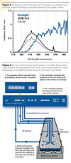
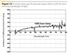
While it is clear that weatherability and light stability are important for many products, the best way to test is sometimes controversial. Various methods have been used over the years. Most researchers now use natural exposure testing, the xenon arc, or the QUV weathering tester. Natural exposure testing has many advantages: it is realistic, inexpensive and easy to perform. However, many manufacturers do not have several years to wait and see if a "new and improved" product formulation is really an improvement. The xenon arc and QUV are the most commonly used accelerated testers. The two testers are based on completely different approaches. The xenon test chamber reproduces the entire spectrum of sunlight, including ultraviolet (UV), visible light and infrared (IR). The xenon arc is essentially an attempt to reproduce sunlight itself, from 295 nm-800 nm (Figure 1).The QUV, on the other hand, does not attempt to reproduce sunlight, just the damaging effects of sunlight that occur from 300 nm-400 nm. It is based on the concept that, for durable materials exposed outdoors, short-wave UV causes the most weathering damage (Figure 1).
Which is the better way to test? There is no simple answer to this question. Depending on your application, either approach can be quite effective. Your choice of tester should depend on the product or material you are testing, the end-use application, the degradation mode with which you are concerned and your budgetary restrictions.
To understand the differences between the xenon and the QUV, it is necessary to first look more closely at why materials degrade.
Triple Threat: Light, Temperature and Moisture
Most weathering damage is caused by three factors: light, high temperature and moisture. Any one of these factors may cause deterioration. Together, they often work synergistically to cause more damage than any one factor alone.
Light
Spectral sensitivity varies from material to material. For durable materials, like most coatings and plastics, short-wave UV is the cause of most polymer degradation. However, for less-durable materials, such as some pigments and dyes, longer-wave UV and even visible light can cause significant damage.
High Temperature
The destructive effects of light exposure are typically accelerated when temperature is increased. Although temperature does not affect the primary photochemical reaction, it does affect secondary reactions involving the by-products of the primary photon/electron collision. A laboratory weathering test must provide accurate control of temperature, and it usually should provide a means to elevate the temperature to produce acceleration.
Moisture
Dew, rain and high humidity are the main causes of moisture damage. Research shows that objects remain wet outdoors for a surprisingly long time each day (8-12 hours daily, on average). Studies have shown that condensation, in the form of dew, is responsible for most outdoor wetness. Dew is more damaging than rain because it remains on the material for a long time, allowing significant moisture absorption.
Of course, rain can also be very damaging to some materials. Rain can cause thermal shock, a phenomenon that occurs, for example, when the heat that builds up in an automobile over the course of a hot summer day is rapidly dissipated by a sudden shower. Mechanical erosion caused by the scrubbing action of rain can also degrade materials such as wood coatings because it wears away the surface, continually exposing fresh material to the damaging effects of sunlight.
The QUV and xenon arc testers each reproduce light, temperature and moisture in different ways.

QUV Weathering Tester
QUV Sunlight SimulationThe QUV is designed to reproduce the damaging effects of sunlight on durable materials by utilizing fluorescent UV lamps. These lamps are electrically similar to the common cool white lamps used in general lighting, but the spectrum they produce is quite different than common fluorescent lamps. The coatings in the glass of the tubes are carefully designed to produce mainly UV rather than visible light or infrared energy.
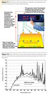
There are different types of lamps with different spectra for various exposure applications. UVA-340 lamps provide the best available simulation of sunlight in the critical short-wave UV region. The spectral power distribution (SPD) of the UVA-340 matches sunlight very closely from the solar cutoff to about 360 nm (Figure 2). UV-B lamps (Figure 3) are also commonly used in the QUV. They typically cause faster degradation than UV-A lamps, but their short-wavelength output below the solar cutoff can cause unrealistic results for many materials.
Control of irradiance (light intensity) is necessary to achieve accurate and reproducible test results. Q-Lab Corporation introduced the Solar Eye Irradiance Controller in 1992. This precision light control system allows the user to choose the level of irradiance. With the Solar Eye feedback-loop system, the irradiance is continuously and automatically monitored and precisely maintained. The monitoring sensors are individually calibrated by the operator on a regular basis. The calibration is traceable to the National Institute of Standards and Technology (NIST) for ISO 9000 compliance.
The Solar Eye automatically compensates for lamp aging or any other variability by adjusting power to the lamps. Figure 4 shows how the irradiance control system works. In the past, it was recommended that lamps in fluorescent testers be rotated every 400 hours. With irradiance control, lamps routinely last over 5,000 hours. The Solar Eye Control system largely eliminates variations in UV intensity and therefore greatly reduces variations in test results.
In the QUV, control of irradiance is simplified by the inherent spectral stability of its fluorescent UV lamps. All light sources decline in output as they age. However, unlike most other lamp types, fluorescent lamps experience no shift in spectral power distribution over time. This enhances the reproducibility of test results and is a major advantage of testing with QUV.

The programmable, automatic irradiance control system allows the operator to choose a higher-than-standard level of irradiance for UV exposure tests. For many materials, this results in faster degradation and therefore shorter test times.1
A major benefit of using the QUV is that it allows the most realistic simulation of outdoor moisture attack. Outdoors, materials are frequently wet up to 12 hours a day. Because most of this moisture is the result of dew, the QUV uses a unique condensation mechanism to reproduce outdoor moisture.
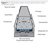
During the QUV condensation cycle, a water reservoir in the bottom of the test chamber is heated to produce vapor. The hot vapor maintains the chamber environment at 100% relative humidity, at an elevated temperature. The QUV is designed so that the test specimens actually form the side wall of the chamber. Thus, the reverse side of the specimens is exposed to ambient room air. Room air-cooling causes the test surface to drop a few degrees below the vapor temperature. This temperature difference causes liquid water to continually condense on the test surface throughout the condensation cycle (Figure 7).
The resulting condensate is very stable, pure distilled water. This pure water increases the reproducibility of test results, precludes water-spotting problems and simplifies QUV installation and operation.

In addition to the standard condensation mechanism, the QUV can also be fitted with a water spray system to simulate other damaging end-use conditions, such as thermal shock or mechanical erosion. The user can program the UV to produce cycles of wetness alternating with UV, a situation that is identical to natural weathering.
The QUV fluorescent weathering tester simulates the damaging effects of sunlight, dew and rain. It is the most widely used weathering tester in the world.
Xenon Test Chamber
Xenon Sunlight Simulation
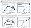
Xenon arc testers are considered the best simulation of full-spectrum sunlight because they produce energy in the UV, visible and infrared regions. To simulate natural sunlight the xenon arc spectrum must be filtered. The filters reduce unwanted radiation and/or heat. Several types of glass filters are available to achieve various spectra. The filters used depend on the material tested and the end-use application. Different filter types allow for varying amounts of short-wave UV, which can significantly affect the speed and type of degradation. There are three commonly used types of filters: Daylight, Window Glass and Extended UV. Figures 8-10 show the spectra that these filters produce. Also included is a close-up look at these spectra in the critical short-wave UV region from about 295 to 400 nm.
Control of irradiance is especially important in a xenon tester, because xenon lamps are inherently less spectrally stable than fluorescent UV lamps. Xenon arc testers are typically equipped with an irradiance control system. The Q-Sun xenon's control system is illustrated in Figure 11.
Most xenon arc testers simulate the effects of moisture through water spray and/or humidity-control systems. The limitation of water spray is that when relatively cold water is sprayed onto a relatively hot test specimen, the specimen cools down. This may slow down the degradation. However; water spray is very useful for simulating thermal shock and erosion. In a xenon arc, highly purified water is necessary to prevent water spotting. Because humidity can affect the degradation type and rate of certain indoor products, such as many textiles and inks, control of relative humidity is recommended in many test specifications. Modern xenon test chambers are available with relative humidity control.
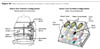
The first rotating-drum light stability testers were developed around 1918 and used a carbon arc as the light source. This device features a central light source or lamp(s), positioned vertically, with a filter system surrounding it. The test specimens are mounted facing the light. The most popular xenon arc version of this tester uses a water-cooling system for its lamp. This is often called a rotating drum tester.
More recent technology features a chamber with one or more air-cooled lamps mounted in the ceiling. In this system, the filters are flat and fitted below the lamps. A reflector system built into the top and the sides of the chamber enhances irradiance uniformity. The test specimens are mounted below the lamps on a tray.
Regardless of the hardware configurations used, modern xenon testers typically have systems to control light intensity (irradiance), temperature and relative humidity (Figure 14).
Optical Filter System
The static-array xenon test chamber uses one or more pieces of flat filter glass for each of its air-cooled xenon lamps. Water-cooled rotating-drum testers use a different system consisting of cylindrical inner and outer filters that fit around the xenon lamp. Each type of xenon arc tester is able to reproduce the full spectrum of sunlight. Research shows that the filters used in static-array testers match sunlight and sunlight through window glass as well as, or better than, the filters used in rotating-drum testers.2
Filter solarization is a potential weakness in xenon arc testers. As rotating-drum filters age due to exposure to UV, they lose their ability to transmit the shorter wavelengths of light. This phenomenon is called solarization. The resulting shift in the spectrum can affect the reproducibility of test results. Consequently, rotating-drum filters must be replaced on a frequent basis. Some static-array's filters have been designed not to solarize with extended use.
Moisture
Both the static-array xenon test chamber and rotating-drum xenon chambers simulate the effects of outdoor moisture by spraying water onto the test specimens. This method is especially good for simulating the effects of thermal shock or mechanical erosion. In the static-array, test specimens are mounted on a flat specimen tray, which is tilted at 5º from horizontal. The static-array's water spray covers the specimens uniformly and, because of the near-horizontal position of the specimens, the water does not quickly run off. In the static-array, specimens stay wet during the entire moisture cycle.
Rotating-drum testers have a spray bar and nozzles that spray the specimens with water as they rotate past it. Specimens are wetted for approximately three seconds out of each one-minute revolution. Because of the vertical position of the specimens, the water quickly runs off the surface. Between these wettings, it is possible for specimens to dry off as they rotate away from the spray.
Sample Mounting
A static array tray accommodates different sizes of flat panels or three-dimensional specimens like parts, components, bottles and test tubes. Rotating-drum testers can only mount flat panels in a vertical position.
Lamp Cooling
Xenon arc lamps produce a lot of heat that must be dissipated. The static-array removes excess heat by means of moving large volumes of air through the lamp housing. The rotating drum uses a water-cooled lamp system. Since water is an excellent heat-transfer agent, this is highly efficient. Consequently, rotating-drum lamps can be operated at a very high wattage to produce high irradiance. Water cooling requires a somewhat complex lamp/filter apparatus with inner and outer filters. The cooling water must be very pure to mitigate any build up of impurities on the lamps and filters.
Irradiance Calibration
The static array irradiance calibration system uses a radiometer and can be performed by the machine operator. A rotating drum tester is calibrated with a multi-step procedure using a special calibration lamp. Generally, calibration of a rotating drum tester is done by an outside service technician.
Uniformity
Research was done to compare the uniformity of degradation of test specimens within an individual chamber of either type.3 Twenty-five different uniformity tests were done. In both the rotating drum and in the static specimen mounting system, the uniformity of degradation with a single chamber varied between ± 3% to ± 13%, depending on the material. The uniformity in the static array tester was as good as, or better than, the rotating drum for some material/exposure conditions.
Report Abusive Comment