Graphite: A Multifunctional Additive for Paint and Coatings
By Albert V. Tamashausky, Technical Services Advisor, Asbury Carbons Inc., Asbury, NJ
Graphite is one of the three, common, naturally occurring forms of carbon (graphite, amorphous carbon, diamond). The word graphite is derived from the Greek word graphein, to write. Common names for graphite include black lead, plumbago and mineral carbon.
Anisotropy
Anisotropy describes a material that has different properties (chemical, physical or both), depending on the crystallographic direction observed. Graphite is the classic example of an anisotropic substance. The anisotropic behavior of graphite is illustrated in its ability to act as a solid film lubricant. Graphene layers, stacked along the "c" crystallographic axis, have high inter-layer strength but low intra-layer cohesion. The weak pi bonding, which holds adjacent sheets in alignment, yields with minimal energy allowing graphene layers to peel away from each other and the crystal. Groups of graphene layers cleaved away from a graphite crystal will provide a tough, impervious, inert, highly lubricious thin film, which will effectively fill and "cap" disparities between rubbing surfaces. The film-forming properties of graphite provide a perfect example of the relationship between microscopic form and macroscopic function.The anisotropic behavior of graphite is exemplified in virtually all of its physical and chemical properties. For example, thermal and electrical conductivity, which result from various modes of within-plane electron transfer, are very high in the direction parallel with graphene layer planes ("a" direction). However, in the "c" axis direction, no "ambient" mechanism of electron transfer exists, resulting in low thermal and electrical conductivity in this direction.
Of course, platelet overlap, crystalline imperfections and some randomness in platelet location in a thin film results in graphite-containing coatings, which typically do show a significant degree of through-plane conduction; however parallel-plane conductivity is usually much higher.
 Courtesy of Asbury Carbons Inc.
Chemical Inertness
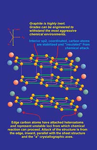
Graphite is composed of carbon atoms, so it will react with oxygen above about 450 degC to form carbon dioxide or carbon monoxide depending on the partial pressure of oxygen. However, most coating systems are composed of binders and other additives, which either oxidize or break down thermally before the oxidation threshold temperature of graphite is reached. In situations where graphite may be intermittently exposed to high temperatures, it has excellent short-term resistance to oxidation. Reactivity between most chemical species and graphite are minimal. This high degree of chemical inertness is a primary attribute of the sp2-hybridized carbon atoms. (see sidebar) Carbon atoms located within graphene layers have a natural inertness as a result of the resonance stability discussed. However, carbon atoms located at edge sites, especially those bonded to heteroatom substituents, are more reactive. Based on this model, chemical reactions typically occur from the "edge in" rather than from the "top down" of a graphene layer (Figure 5). This occurs due to the "unbalanced" edge atoms, which tend toward less-stable bonding types since the sp2 pi bond system becomes discontinuous at the "edge environment." Also, dangling bonds that are attached to edge carbons typically are coupled to volatile species such as oxygen, hydrogen, nitrogen, hydroxyl and other "groups" that are less stable in thermally or chemically aggressive environments. Removal of these species results in carbon atoms, which are unstable and reactive. In an oxidizing atmosphere at high temperature, these destabilized carbon atoms can be "gasified" by oxygen, etc., and then diffuse away from the graphite surface. The result is another group of carbon atoms left behind for further attack. The reaction will proceed from the edge inward until oxidation of carbon is complete.
In a reducing atmosphere, graphite is one of the most refractory materials known. Graphite is stable to well above 3000 degC as long as no oxygen or oxidizing species are present. Under ambient to moderately high temperatures, graphite will not act as a reducing agent due to the strong intralayer bonding between carbon atoms. The result is that graphitic carbon is relatively un-reactive, even when finely divided. In most ambient conditions, graphite particles (free from admixed materials) as fine as three microns in size, will not form explosive mixtures with air.
 Courtesy of Asbury Carbons Inc.
Electrical Conductivity: Qualitative Theory
One of the most interesting aspects of graphite as a material is that even though it is a non-metal, it is still a good conductor of electricity. However, as with all of its other physical properties, the magnitude of its electrical conductivity can be resolved in terms of structure and bonding.
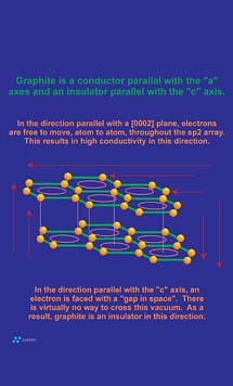
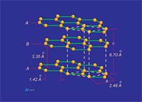
Conduction occurs when a pathway for electron transfer exits. Molecular bonds that tend to "trap" electrons between two adjacent atoms, as in the sigma orbitals between adjacent carbon atoms in a graphene layer or diamond structure, do not provide a pathway suitable for electrons to flow. However, as noted in the sidebar, the pi bonding network that resides above and below a graphene layer allows for the delocalization of electrons between all carbon atoms within the graphene layer. This results in an electronic pathway that is as large as the graphene layer itself. Electronic conduction within the two-dimensional confines of this system is "perfect" and is actually comparable in magnitude to the electronic conduction in silver. However, no electronic pathway exists between adjacent graphene layers since the 3.35 A spacing between graphene layer planes acts as an electrically insulative "vacuum" to electron transfer (Figure 6). For this reason, graphite is not conductive between layers (parallel with "c" crystallographic axis). The result is that although graphite is a good conductor of electricity, the addition of the "c" axis component to the equation results in a bulk conduction lower than most conductive metals.
Electrical Conductivity: Application
The discussion above is restricted to the graphite single crystal. Practical application of graphite powder utilizes primary particles, which, depending on the type, are more or less composite in structure. Electrical pathways in these particulates can be concentric, overlapping, tortuous, circuitous and generally discontinuous in nature. Interparticle porosity also affects conductive pathways. In addition, the mechanical handling required to manufacture powdered graphite adds further to the degree of crystalline imperfection of these particles. The result is a particle that diverges greatly from true anisotropic behavior. These facts, combined with the random motion of particles in a liquid flow field during coating application, results in coatings that do have some degree of isotropy with respect to the physical properties imparted by graphite. If graphite in application were truly anisotropic, then coatings, articles, etc., made from graphite would conduct in only one direction. Although conduction does tend to be higher in the direction parallel with the surface to which the graphite is applied, all paints and coatings containing graphite will realize through-plane electrical conduction.
Conductivity in coatings is a strong function of particle size. This is true because finer materials tend to have shorter electronic pathways, and more particles per unit volume of coating mean more particle-particle gaps that must be traversed by electrons. However, fine particles result in better "dispersion" of conductive media through the coating matrix. In application, graphite powders can be utilized as highly effective conductive fillers, especially when thought is given to multi-modal particle size distributions with the goal of optimizing "space filling" within the coating matrix. The conductive effect of graphite fillers can be further enhanced by the addition of conductive carbon black, at low addition rates, to provide electrical continuity between graphite particles.
 Courtesy of Asbury Carbons Inc.
Thermal Conductivity: Theory
Thermal conduction in graphite occurs as the result of the movement of thermal vibrations across the sigma bonds that connect carbon atoms within a graphene layer. This functionality is provided via sigma-bonding electrons. The between-carbon atom bond length in graphite is 1.41 A. This relatively short bond length combined with the well-developed "connectivity" of in-plane carbon atoms results in an extremely efficient "thermal delivery system." In fact, the thermal conductivity parallel to graphene layer planes is comparable to the thermal conductivity in the most conductive solid known: diamond. However, as with electrical conduction, the "c" axis between-layer-component of thermal conduction is very low due to the 3.35 A "vacuum" separating adjacent graphene layers. Thermal vibrations cannot effectively jump this gap, so in the "c" axis direction conduction is almost 200 times lower than the in-plane direction conduction (Figure 7).Thermal Conductivity: Application
The same forces as those described above for electrical conduction dictate the "real" conductive properties of granular and powdered graphite.Graphite can be used as a "thermal" additive in paint and coating systems where it functions in a number of ways. Since most graphite powders have laminar or flake-like morphology they tend to orient parallel to the coated substrate. In this mode of orientation, interconnectivity between particles is developed by the overlap, or edge contact of adjacent particles. An analysis of general principles will prove that most thermal energy leaves and enters crystal edges, or domains where edge environments are present, i.e., prismatic steps present on the basal planes.
Once the coating dries or sets, the graphite acts as a thermal material by not only effectively absorbing radiant energy, but by conducting it away from the "hot zone" through parallel substrate conduction. Graphite addition to paints and coatings can reduce "hot spots" and, therefore, increase the overall thermal stability of a coating in an environment where radiation heat transfer is an issue.
Although graphite is more effective at conducting heat parallel with the substrate to which it is applied, through-plane conductivity also occurs (see Electrical Conductivity: Application). In through-plane conduction, graphite transfers heat through the coating, into or out of the substrate. This means that a hot substrate can cool through conduction and surface radiation even though it is coated. Coating surfaces of objects that radiate heat may actually increase the rate of heat transfer from these objects.
Provided that the temperature of the environment is below 450 degC, graphite present in a paint or coating will not "gasify" due to oxidation. In a reducing atmosphere, graphite is stable above the temperature where most metals liquefy (3000 degC). In paint and coating systems, graphite is typically the least thermally sensitive material present in a formulation and the most thermally functional.
 Courtesy of Asbury Carbons Inc.
Cleavage - Lubricity and Flexibility
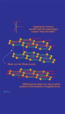
Cleavage is a material property that describes the propensity of a mineral to break along planes of weakness. These planes of weakness are a reflection of the internal molecular or atomic structure of the crystal. The "degree of cleavage" is based upon the ease that a particular mineral shows in separating parallel to a specified crystallographic direction. Cleavage can be described as highly perfect, perfect, good, fair, poor, etc., referenced to any direction of interest. For example the minerals fluorite and diamond have perfect cleavage parallel to {111}(the octahedral face). A cube of fluorite or diamond could be "cleaved" into a perfect octahedron with very little effort. The other extreme is the mineral quartz, which does not show distinct cleave in any direction. Any attempt to cleave quartz will result in uneven fractures.Graphite has perfect cleavage parallel to the {0001} basal pinacoid. This direction just so happens to be in perfect alignment with the graphene layers that make up a graphite crystal. The cleavage plane in question is controlled by the presence of the weak pi bonds discussed earlier. Cleavage in graphite is what allows graphite to be flexible, to flow under pressure and to "film-form." The filming ability of graphite is what provides the anti-friction properties graphite is known for. The frictional properties of graphite are difficult, if not impossible to separate from its cleavage properties: in reality they are both macroscopic functions that result from the same atomic level form (Figure 8). The greasy or characteristic "slippery" feel of graphite results from the release of cleaved graphene layers as one rubs a graphitic surface. Again, this release of graphite layers is actually active cleavage of the graphite crystal.
Graphite, especially flake graphite, is flexible. This attribute may provide a benefit in a coating or paint application since the flexible nature of the graphite filler is realized by increased flexibility in the coating. Graphite is flexible because as a graphite flake is curled, graphene layers are able to move relative to one another. As tensile and compressive forces develop during flexing, individual graphene layers "adjust" their positions to relieve stress that builds between the layers (Figure 5). Although flexing does not actually result in cleavage, both attributes are intimately related to the weak secondary electrical forces (pi bonds) that hold graphene layers together.
 Courtesy of Asbury Carbons Inc.
The Four Primary Forms of Graphite
Four types of graphite are used commercially as additives in paint and coating systems, as well as other industrial applications; synthetic, flake, crystalline vein and amorphous graphite. Each type of graphite has attributes, which determine its effectiveness in a given coating application.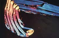 Courtesy of Asbury Carbons Inc.
1. Flake Graphite
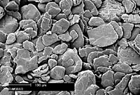
Flake graphite, as indicated by the name, has a flaky morphology. Most flake graphite is formed in a high-grade (high temperature and pressure), metamorphic geologic environment by the heat and pressure metamorphism of dispersed organic material. Flake graphite is removed from its enclosing "ore" rock by crushing the rock and separating the graphite flakes by froth flotation.
"Run-of-mine" flake graphite is available in purities between 80 and 98 percent carbon. Most processors are also capable of supplying 99% carbon flake graphite through various additional purification methods. The impurities in flake graphite are virtually identical in composition to the enclosing ore rock.
Due to its impervious laminar structure, flake graphite is an effective coating additive. When properly dispersed, overlapping graphite lamella form a tough, impervious coating, which is lubricious, inert, and both electrically and thermally conductive. Also, flake graphite is non-photo reactive and will not be bleached or effected by ultraviolet light.
Flake graphite is available in sizes ranging from 0.5-mm flakes to 3-micron powder (0.003 mm). The morphology of flake graphite is consistently laminar regardless of particle size. By adjusting the rheology of the system, flake of almost any size can be used effectively in paints and coatings (Figures 9a-9b).
 Courtesy of Asbury Carbons Inc.
Intumescent Flake Graphite
Also known as "expandable graphite," intumescent flake graphite is a synthesized intercalation compound of graphite that expands or exfoliates when heated. This material is manufactured by treating flake graphite with various types of intercalation reagents. These reagents migrate between the graphene layers in a graphite crystal and remain as stable species. If exposed to a rapid increase in temperature, these intercalation compounds decompose into gaseous products, which result in high inter-graphene layer pressure. This pressure develops enough force to push apart graphite basal planes in the "c" axis direction (Figure 10). The result is an increase in the volume of the graphite of up to 300 times, a lowering of bulk density and approximately a 10-fold increase in surface area. Intumescent graphite is used as a fire-suppressant intumescent additive, as a raw material to manufacture graphite gasket products, as a foundry additive and in other industrial applications.When added to coatings, intumescent graphite can act in various ways as a fire suppressant. Suppression may be affected by the following mechanisms:
- 1. Formation of a char layer: Expanded graphite will form a "char" layer between the flame or heat front, and the substrate. This layer provides a shield, which effectively insulates the substrate from radiant heat, oxygen and direct contact from flames.
2. Endothermic absorption: The action of graphite exfoliation is endothermic. Expandable graphite exposed to heat, particularly from a flame front, will absorb heat during the exfoliation reaction, effectively removing heat from the source.
3. Out-gassing: The exfoliation reaction is accompanied by out-gassing as intercalation reagents decompose and escape as gaseous decomposition products. Up to 20% of the intumescent graphite mass may be lost as non-flammable gaseous products. These gases may act to displace oxygen in an advancing flame front.
Intumescent graphite is available in purity ranging from 80-99% carbon. Both coarse and fine grades are available. The degree of intumescences, also know as "expandability" generally ranges from 80 times to 300 times volume increase. Products can be specified as low (acidic), neutral and high (alkaline) pH to allow compatibility with a variety of aqueous and non-aqueous systems.
Although intumescent graphite has been utilized for many years in various applications, it is relativity new to the paint and coatings industry. This unique product may prove to be a keystone in the development of fire-retardant coatings to meet the demands of 21st century applications.
 Courtesy of Asbury Carbons Inc.
2. Crystalline Vein Graphite
Crystalline vein graphite is unique, as it is believed to be naturally occurring pyrolytic (deposited from a fluid phase) graphite. Vein graphite gets its name from the fact that it is found in veins and fissures in the enclosing "ore" rock (Figure 11). This variety of graphite is formed from the direct deposition of solid, graphitic carbon from subterranean, high-temperature fluids known as pegmatitic fluids. Pegmatites can form regionally or locally when a subterranean mass of magma cools, or when some other source of "geologic energy" results in melting of the country rock. These fluids are hot under high pressure and are erosive. Pegmatitic fluids may be supercritical. If such fluids invade a previously existing flake graphite deposit or other carbonaceous-bearing rock, the solid carbon present can become incorporated into the fluid as carbon dioxide, methane, carbon monoxide, etc. Carbon-containing gases can also form from the reaction of carbonate mineral species within the local geology. If a limestone, marble or other carbonate-rich mineral species is intruded by magma or other energy source, large volumes of carbonaceous gases can potentially form.Regardless of the mode of gas/fluid generation, carbon is mobilized and transported through fractured country rock to a location more or less remote from the volume where the gas/fluid was formed. Where equilibrium conditions are right, solid graphitic carbon "precipitates" directly from the fluid phase.
This type of graphite typically shows needle-like macro morphology and flake-like micro morphology.
Due to the natural fluid-to-solid deposition process, vein graphite deposits are typically above 90% pure, with some vein graphite actually reaching 99.5% graphitic carbon in the "as-found" state. Vein graphite is mined using conventional shaft or surface methods. Although several small deposits of this type of graphite are known to exist worldwide, Sri Lanka is the only area presently producing commercially viable quantities of this unique mineral.
In paint and coating applications, vein graphite may offer superior performance since it has slightly higher thermal and electrical conductivity, which result from its high degree of crystalline perfection. Also, vein graphite has good oxidation resistance and is highly lubricious. Commercial grades are available from 85-99% carbon. Sized materials from 1 inch to 3 micron are available.
 Courtesy of Asbury Carbons Inc.
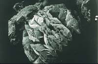
3. Amorphous Graphite
Amorphous graphite is the least "graphitic" of the natural graphites. However, the term "amorphous" is a misnomer since this material is truly crystalline. This graphite variety is "massive" with a microcrystalline structure (anhedral), as apposed to flake and vein, which both have relatively large, visible crystals (euhedral) (Figure 12). Most commercial-grade material is formed from the contact or regional metamorphism of anthracite coal. It is considered a seam mineral and is extracted using conventional, coal-type mining techniques. Contact metamorphism may result when a geological energy source, such as an igneous intrusion, contacts the coal seam. At the point of contact, and for some distance from the point of contact, the heat associated with the intrusion, or other local energy source, drives the graphitization of the coal. The same amorphous-to-crystalline phase transformation of carbon may occur on a more regional basis in regional metamorphism where the agent of change is larger, such as an intruded stock or batholithic structure.Most of the current supply of amorphous graphite available in the United States is imported from Mexico and China.
Amorphous graphite is typically lower in purity than other natural graphites. This is due to the intimate contact between the graphite "micro crystals" and the mineral ash with which it is associated. This close graphite/ash association makes floatation and other density- and chemical-based separation techniques inefficient, if not impossible. Commercial grades of amorphous graphite are available from 75-85% purity and sizes from 4-inch lumps to 3-micron powder.
Amorphous graphite tends to be much less reflective in both large- and small-grained sizes. Therefore, it has a darker color, bordering on black, while other natural graphite has a color closer to "silver-gray." This makes amorphous graphite useful in coatings, which require less reflectance. Also, this graphite variety is typically lower in cost than other types but is still lubricious, conductive and chemically stable.
 Courtesy of Asbury Carbons Inc.
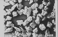
4. Synthetic Graphite
Also known as "artificial graphite," this variety is a man-made product. Synthetic graphite is manufactured by heat-treating amorphous carbons, i.e. calcined petroleum coke (CPC), pitch coke, etc., in a reducing atmosphere to temperatures above 2500 deg C. At high temperatures, the "pre-graphitic" structures present in these "graphitizable carbons" become aligned in three dimensions. The result is the transformation of a two-dimensionally ordered amorphous carbon into a three-dimensionally ordered crystalline carbon.Petroleum- or coal-based feedstock for coke and subsequent synthetic graphite production are chosen from product streams that have a high concentration of aromatics. In other words, these materials are high in substances containing, or that tend to form, high-molecular-weight polynuclear aromatic structures. Since the graphene layers described earlier are built from large arrays of aromatic ring structures, graphite production is based on carbons that are inherently rich in these materials. The high temperature of ambient pressure graphitization provides the driving force to coalesce aromatic rings into large, two-dimensional arrays, as well as provide the energy required for "c" axis alignment of graphene layers.
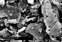
The morphology of synthetic graphite is generally a function of particle size. For particles larger than about 20 microns, the macroscopic morphology is very similar to the coke feed used to manufacture the graphite (Figure 13). However, all graphite is based on a flaky, "basic structural unit," and as size is reduced below about 20 microns this flake structure becomes apparent in the primary particle (Figure 14). Finely ground synthetic has a flaky structure.
Synthetic graphite is typically available in purities above 99%. High purity is the rule, rather than the exception with this material because feed-stocks used to make synthetic graphite are typically petroleum-based materials that are inherently low in mineral impurities, and the manufacturing method tends to sweep out impurities, which become vaporized at the high process temperatures.
This variety of graphite is available in sizes from 1/2 inch down to 3 microns. Synthetic graphite is used in many paint and coating applications where higher purity is required. It is compatible with virtually any aqueous or non-aqueous system, has excellent thermal and electrical conductivity, is chemically inert and relativity low in cost.
 Courtesy of Asbury Carbons Inc.
Conclusion
Graphite is an effective, low-cost additive that is multi-functional when utilized in paints, coatings and a myriad of other industrial applications. Graphite provides chemical inertness, refractoriness, electrical conductivity, thermal conductivity, lubricity, UV stability, and in the case of "expandable" graphite, fire-retardant properties. Graphite is non-toxic. With proper rheological adjustment, graphite is compatible with most aqueous and non-aqueous coating systems. Graphite is available in "off-the-shelf" purities from 80% to 99+% carbon, and sizes from large grains down to 3-micron powder. Particle distributions can be tailored to meet almost any liquid system requirement.For more information, contact Albert V. Tamashausky, Director of Technical Services, Asbury Graphite Mills, Inc., 405 Old Main St., Asbury, NJ 08802; phone 908/537.2155; e-mail technicalservicesinfo@asbury.com.
Side bar: Graphite
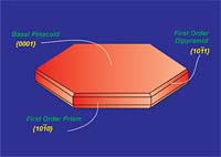
Graphite is a hexagonal mineral (Figures 1 and 2) and crystallizes in the 6/m2/m2m crystal class. Common forms (crystal faces) include the {0001} basal pinacoid, {1010} prism and {1011} pyramid. Graphite has perfect cleavage parallel to {0001} (perfect basal cleavage). The calculated crystallographic density of graphite is 2.26 g/cc. Depending upon the purity, the measured specific gravity is approximately 2.20 to 2.30. Graphite containing higher levels of ash tends to show higher density due to the fact that most ash constituents have a specific gravity greater than 2.26.Graphite is gray to black in color, opaque to visible light even in thin section and has a metallic luster. It is soft, with a Mohs hardness of 1-2 (Mohs 1=talc, Mohs 2=gypsum, Mohs 10=diamond) and is flexible but not elastic. Graphite has high thermal and electrical conductivity, is highly refractory and chemically inert.
Basic Structural Description
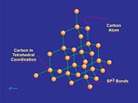
Graphite is composed of carbon atoms that are arranged in poly-aromatic, hexagonal ring arrays. These arrays can be looked at as an infinite series of fused benzene rings without the hydrogen atoms. Carbon atoms in these arrays are in the sp2-hybridized state. In the sp2 molecular orbital model (Figure 3), each carbon atom is typically attached to three other species, three other carbon atoms in the case of graphite. In this bonding mode, the bond angle of carbon is 120 deg. Ring arrays form sheets of carbon atoms, and individual sheets are known as graphene layers. Graphene layers are stacked one on top of another, parallel with the "c" crystallographic axis of the hexagonal 4-axis system in which graphite crystallizes.Within each graphene layer, carbon-to-carbon bonding is strong covalent sigma-type bonding. This bonding is the result of overlap of the sigma electronic orbitals acting between adjacent carbon atoms. These are "hard" bonds and are similar in character to the pure sp3-type bonds, which form the three-dimensional, giant molecular structure of diamond. Each carbon atom within the graphene layer has three of these sigma atomic orbitals, which combine with similar orbitals of adjacent carbon atoms, forming the molecular bonds that hold the layer together (Figure 4a).


Individual graphene layers are held in stacked arrangement by the second component of the sp2 model, known as the pi component or pi bond. This pi component is the result of weak, secondary electrical bonds formed by overlapping pi (π) orbitals of the sp2 carbon network within each graphene sheet. Each carbon atom has one pi electron, which has a high probability of being found in a region just above or below the plane formed by the carbon atoms in a graphene layer. Since each graphene layer can be viewed as a system of fused, six-carbon rings, one can also imagine that superimposed above and below each ring there exists a donut-shaped region, containing six pi electrons (one from each carbon atom)(Figure 4a). These pi electrons are not stationary, but are "de-localized" within the confines of the donut-shaped region they occupy. This de-localization of pi electrons results in what is known as resonance energy or resonance stability. The stability here is chemical stability, which is spread throughout the entire graphite structure. In non-quantum terms, the effect is one of "spreading" out the electrical charge across the entire array of carbon atoms.

References
Dana, E.S.; Ford, W.E. Dana's Textbook of Mineralogy; Wiley & Sons: New York, 1949.Harlow, G.E. The Nature of Diamonds; Cambridge University Press: New York, 1998.
Mantel, C.L. Carbon and Graphite Handbook; Wiley & Sons: New York, 1968.
Marsh & Reinoso. Sciences of Carbon Materials; Publications of the Universidad de Alicante, 1997.
Paxton, R.R. Manufactured Carbon: A Self-Lubricating Material for Mechanical Devices; CRC Press: Boca Raton, FL, 1979.
Pierson, H.O. Handbook of Carbon, Graphite, Diamond, and Fullerenes; Noyes Publications: Park Ridge, NJ, 1993.
West. CRC Handbook of Chemistry and Physics; CRC Press: Boca Raton, FL, 1983.
Looking for a reprint of this article?
From high-res PDFs to custom plaques, order your copy today!


