Ultraviolet (UV) Measurement for Formulators: Part II
This article examines the parameters of
wavelength, peak irradiance and energy density that comprise UV curing as well
and some common issues related to measuring them.

Much of the commercial literature concerning UV measurement has been targeted to end users and addresses issues such as process monitoring, benchmarking and troubleshooting UV cure problems. However, another important audience for measurement are suppliers of UV chemistry and equipment who must communicate clearly with end users about process specifications. While the end user is often concerned with changes in UV measurement, the supplier is frequently trying to communicate some absolute measurement. This two-part article endeavors to help bridge the gap between the laboratory and the production line.
In Part I of this article the fundamental parameters of wavelength, peak irradiance and energy density (dose) were discussed as well as their role in the curing process. We also introduced some concepts related to the accuracy and repeatability of intensity measurements such as band-pass filtering, cosine response, solarization and temperature stability. We concluded with some guidelines for writing a comprehensive curing specification. In Part II we look at some issues regarding energy density measurement, the effect of lamp optics on measurement, calibration, and conclude with some suggestions on selecting a measurement instrument.
Sampling Rate
Measuring UV energy density is commonly achieved by making a number of successive intensity measurements and summing them together.
This concept is a familiar basic idea of elementary integral calculus. The energy density is the “area” under the curve of intensity over time. The finer slices we make, the better our estimate of the total energy density will be. This is of course a function of the sampling speed of the radiometer.
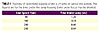
The importance of sample rate is magnified when you consider that many UV-curing processes happen at very high speeds, and measuring them requires some attention to this fact. Consider what happens if a UV integrating radiometer is placed on a conveyor belt that moves under a fixed lamp. Suppose for example the lamp has a profile as shown in Table 1. Let us say for this example that the effective illuminated width of the lamp is 2.5 inches (some highly focused systems are as narrow as one inch).
Now consider how many samples can be taken at various sample rates. A slow sample rate of say 25 samples per second means that on a 10-feet-per-minute conveyor 31 samples are collected. But on a 200-fpm conveyor only one measurement can be taken while the radiometer is within the illuminated “window”. What is the likelihood that this measurement will be useful?
 The situation is analogous to trying to take a
close up photograph of a racecar with a camera. It’s hard to get much with a
single snapshot – in fact it may be hard to capture the car at all let alone
get it in exactly the center of the frame. Hence the need for high-speed data collection.
The situation is analogous to trying to take a
close up photograph of a racecar with a camera. It’s hard to get much with a
single snapshot – in fact it may be hard to capture the car at all let alone
get it in exactly the center of the frame. Hence the need for high-speed data collection.
By analogy, at faster line speeds, a faster shutter speed with a motorized drive is needed. Today’s radiometers offer sample rates of 2048 per second or more. At line speeds of 200 fpm this means that over 120 samples are taken in the short 2-inch window used in our example. This kind of sample rate permits an accurate picture of both the true peak irradiance and the energy density. The slices under the curve are very fine and provide an accurate measurement. Often the best practice is to take readings at a slower rate and extrapolate the values.
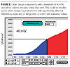
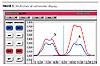
Another application affected by sample rates is the emerging use of flash lamps, such as Xenon UV sources. Unlike a continuous UV source, like a camera flashbulb, these sources supply a very high, but very short-lived burst of UV light. These lamps may pulse very quickly, in the range of 100-120 times per second (Figure 1).
This places two demands on measurement: very fast data acquisition and the ability to handle a high instantaneous peak of energy. Units have been specially designed to measure these sources since conventional radiometers can significantly under-report the output of these pulsed lamps.
 Threshold
Many measurement devices have a threshold, or “trigger point”, at which they begin to collect data. On integrating radiometers where a large amount of data must be stored, a threshold ensures that memory is reserved for real data. Thresholds also prevent measuring stray UV from windows, fluorescent lamps or reflected light that is not part of the cure process.
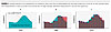
 But it is important to understand the threshold level of your radiometer
and to determine whether the threshold will adversely affect any data from
being collected that would be missed (Figure 3). Low-level irradiance processes
for example may require setting a lower threshold, or selecting a device with
an appropriate trigger point. Very slow line speed processes and low irradiance
applications measured with devices of differing threshold will result in
inconsistent data.
But it is important to understand the threshold level of your radiometer
and to determine whether the threshold will adversely affect any data from
being collected that would be missed (Figure 3). Low-level irradiance processes
for example may require setting a lower threshold, or selecting a device with
an appropriate trigger point. Very slow line speed processes and low irradiance
applications measured with devices of differing threshold will result in
inconsistent data.
Accuracy, Precision and Calibration
In order to put trust into our measurements, we must understand not only the causes of variation, but what may be expected. Well-designed radiometers have a high degree of precision, or repeatability, if properly used under the same conditions. But the accuracy of these devices may vary over time and if test conditions change. Readings between different radiometers from different manufacturers will vary widely depending on the quality of construction and their engineering design. We have already seen how the optical stack and the selection of band-pass filters will produce different measurements of the same source.
Over time, both the electronic circuitries as well as optical components change. Changes can be exaggerated if there is continuous exposure to UV or exposure to very high-intensity sources, which accelerate solarization of the optical components.
While a repeatable, or precise device may suffice for end users who are interested in relative measurements and changes in their process, more attention to accuracy is needed for suppliers. Over the wide dynamic range that many broadband radiometers are used, ±10% accuracy is considered very good. Some instruments typically deliver even better accuracy in the neighborhood of ± 5%. Therefore for a reading of 1.2 watts/cm2 the actual irradiance may well be 1.08 to 1.32 watts.
In order to assure accuracy, the radiometer should be periodically calibrated, not less than once a year, and more if there is continuous or high-intensity exposure to sources or some other reason to suspect a shock to the instrument. Between recalibrations, proper maintenance, adherence to temperature limits and care of the optical surfaces should be observed.
Most reputable suppliers provide a certificate of calibration tied to a NIST-traceable source with this service. If your radiometer is used routinely with a particular light source, such as an Iron additive lamp, or a 395 nm LED, you should communicate this information to your radiometer supplier so they can calibrate with a similar UV source for even greater accuracy.

1. Use a device that is also likely to be used by your customer. It does little good to specify cure values with an instrument nobody but your own bench chemists have access to. While some lab equipment may provide features or accuracy that are attractive in lab work, a second measurement on a popular field tool will be appreciated by customers and tech support. Specifications, especially in UV measurement, are very device dependant. Some affordable, robust, easy-to-use radiometers are popular in the plant and measurements on these instruments should be provided.
As a corollary, for customers new to UV, your guidance on what instrument to use will be helpful and also facilitate communication and ease troubleshooting.
2. Consider the type of sensor that best suits the application. Belt radiometers are great for a wide range of applications, but are occasionally too large for some applications where a miniature device may be needed, or a probe-style sensor used instead.
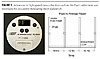
 3. Data accumulation/reporting. Multichannel
radiometers (Figure 5) provide more information than single-channel units that
may be helpful in establishing and troubleshooting cure problems. Being able to
make measurements and export the data into reports for recordkeeping is a good
practice and minimizes errors. Some units have powerful graphical software that
can help analyze problems your customers may not recognize. In the field, a
radiometer that provides a simple numeric display as well as download
capability for more advanced analysis is an ideal
combination.
3. Data accumulation/reporting. Multichannel
radiometers (Figure 5) provide more information than single-channel units that
may be helpful in establishing and troubleshooting cure problems. Being able to
make measurements and export the data into reports for recordkeeping is a good
practice and minimizes errors. Some units have powerful graphical software that
can help analyze problems your customers may not recognize. In the field, a
radiometer that provides a simple numeric display as well as download
capability for more advanced analysis is an ideal
combination.
Some models are well designed for multiple lamp systems since they can display the UV irradiance and energy density of each lamp on a line for diagnostics. Recent advances in communication architecture and miniaturization has resulted in innovative systems such that allow multiple sensors to be positioned on complex 3D parts and report data to a central data collection unit for reporting.
4. Service and support are important, as even a great instrument needs recalibration and service. Work with suppliers who have a depth of knowledge and track record in the industry.
This article examined the parameters of wavelength, peak irradiance and energy density that comprise UV curing as well and some common issues related to measuring them. The goal is to create a language that can be used to discuss a process across the supply chain and provide a way to reproduce in the field what was done in the lab and troubleshoot when necessary. To this end, the proper selection, use and maintenance of UV measurement tools is critical to documenting, communicating and reproducing UV curing processes. br>
Acknowledgement: The author wishes to acknowledge the assistance of Jim Raymont of EIT Instrument Markets of Sterling, VA, for his many contributions to this article. Jim can be reached at jraymont@eitinc.com or by phone at 703/478.0700. Contact the author at PMillsOH@aol.com or visit www.eitinc.com.
Much of the commercial literature concerning UV measurement has been targeted to end users and addresses issues such as process monitoring, benchmarking and troubleshooting UV cure problems. However, another important audience for measurement are suppliers of UV chemistry and equipment who must communicate clearly with end users about process specifications. While the end user is often concerned with changes in UV measurement, the supplier is frequently trying to communicate some absolute measurement. This two-part article endeavors to help bridge the gap between the laboratory and the production line.
In Part I of this article the fundamental parameters of wavelength, peak irradiance and energy density (dose) were discussed as well as their role in the curing process. We also introduced some concepts related to the accuracy and repeatability of intensity measurements such as band-pass filtering, cosine response, solarization and temperature stability. We concluded with some guidelines for writing a comprehensive curing specification. In Part II we look at some issues regarding energy density measurement, the effect of lamp optics on measurement, calibration, and conclude with some suggestions on selecting a measurement instrument.
Energy Density Measurement and Sources of Error
Measuring energy density, or ‘dose’, is intimately related to irradiance since energy density measurements involve calculations directly related to irradiance measurement. So, any error in measuring irradiance will necessarily produce a corresponding error in dose calculations. That said, there are some aspects of energy density that are independent of irradiance measurement.Sampling Rate
Measuring UV energy density is commonly achieved by making a number of successive intensity measurements and summing them together.
This concept is a familiar basic idea of elementary integral calculus. The energy density is the “area” under the curve of intensity over time. The finer slices we make, the better our estimate of the total energy density will be. This is of course a function of the sampling speed of the radiometer.
The importance of sample rate is magnified when you consider that many UV-curing processes happen at very high speeds, and measuring them requires some attention to this fact. Consider what happens if a UV integrating radiometer is placed on a conveyor belt that moves under a fixed lamp. Suppose for example the lamp has a profile as shown in Table 1. Let us say for this example that the effective illuminated width of the lamp is 2.5 inches (some highly focused systems are as narrow as one inch).
Now consider how many samples can be taken at various sample rates. A slow sample rate of say 25 samples per second means that on a 10-feet-per-minute conveyor 31 samples are collected. But on a 200-fpm conveyor only one measurement can be taken while the radiometer is within the illuminated “window”. What is the likelihood that this measurement will be useful?
By analogy, at faster line speeds, a faster shutter speed with a motorized drive is needed. Today’s radiometers offer sample rates of 2048 per second or more. At line speeds of 200 fpm this means that over 120 samples are taken in the short 2-inch window used in our example. This kind of sample rate permits an accurate picture of both the true peak irradiance and the energy density. The slices under the curve are very fine and provide an accurate measurement. Often the best practice is to take readings at a slower rate and extrapolate the values.
Another application affected by sample rates is the emerging use of flash lamps, such as Xenon UV sources. Unlike a continuous UV source, like a camera flashbulb, these sources supply a very high, but very short-lived burst of UV light. These lamps may pulse very quickly, in the range of 100-120 times per second (Figure 1).
This places two demands on measurement: very fast data acquisition and the ability to handle a high instantaneous peak of energy. Units have been specially designed to measure these sources since conventional radiometers can significantly under-report the output of these pulsed lamps.
Many measurement devices have a threshold, or “trigger point”, at which they begin to collect data. On integrating radiometers where a large amount of data must be stored, a threshold ensures that memory is reserved for real data. Thresholds also prevent measuring stray UV from windows, fluorescent lamps or reflected light that is not part of the cure process.
Accuracy, Precision and Calibration
In order to put trust into our measurements, we must understand not only the causes of variation, but what may be expected. Well-designed radiometers have a high degree of precision, or repeatability, if properly used under the same conditions. But the accuracy of these devices may vary over time and if test conditions change. Readings between different radiometers from different manufacturers will vary widely depending on the quality of construction and their engineering design. We have already seen how the optical stack and the selection of band-pass filters will produce different measurements of the same source.
Over time, both the electronic circuitries as well as optical components change. Changes can be exaggerated if there is continuous exposure to UV or exposure to very high-intensity sources, which accelerate solarization of the optical components.
While a repeatable, or precise device may suffice for end users who are interested in relative measurements and changes in their process, more attention to accuracy is needed for suppliers. Over the wide dynamic range that many broadband radiometers are used, ±10% accuracy is considered very good. Some instruments typically deliver even better accuracy in the neighborhood of ± 5%. Therefore for a reading of 1.2 watts/cm2 the actual irradiance may well be 1.08 to 1.32 watts.
In order to assure accuracy, the radiometer should be periodically calibrated, not less than once a year, and more if there is continuous or high-intensity exposure to sources or some other reason to suspect a shock to the instrument. Between recalibrations, proper maintenance, adherence to temperature limits and care of the optical surfaces should be observed.
Most reputable suppliers provide a certificate of calibration tied to a NIST-traceable source with this service. If your radiometer is used routinely with a particular light source, such as an Iron additive lamp, or a 395 nm LED, you should communicate this information to your radiometer supplier so they can calibrate with a similar UV source for even greater accuracy.
Selecting a Radiometer
Hopefully the preceding discussions have pointed out some of the technical aspects of radiometer use and shed light on features such as the optics, sampling rate, threshold settings, temperature stability and precision of devices. Current technology provides for informative real time displays for field use and data download capability for later analysis (Figure 4). There are, however, some practical considerations to bear in mind as well.1. Use a device that is also likely to be used by your customer. It does little good to specify cure values with an instrument nobody but your own bench chemists have access to. While some lab equipment may provide features or accuracy that are attractive in lab work, a second measurement on a popular field tool will be appreciated by customers and tech support. Specifications, especially in UV measurement, are very device dependant. Some affordable, robust, easy-to-use radiometers are popular in the plant and measurements on these instruments should be provided.
As a corollary, for customers new to UV, your guidance on what instrument to use will be helpful and also facilitate communication and ease troubleshooting.
2. Consider the type of sensor that best suits the application. Belt radiometers are great for a wide range of applications, but are occasionally too large for some applications where a miniature device may be needed, or a probe-style sensor used instead.
Some models are well designed for multiple lamp systems since they can display the UV irradiance and energy density of each lamp on a line for diagnostics. Recent advances in communication architecture and miniaturization has resulted in innovative systems such that allow multiple sensors to be positioned on complex 3D parts and report data to a central data collection unit for reporting.
4. Service and support are important, as even a great instrument needs recalibration and service. Work with suppliers who have a depth of knowledge and track record in the industry.
Summary
Like the old joke says, “Some people use statistics like a drunk uses a light post, more for support than illumination.” Imagine if formulas were expressed in uncertain units using irreproducible tools. Just “add some photoinitiator to a little bit of monomer and mix it for a while” will not produce a reliable coating – and playing fast and lose with curing specifications will not provide the plant with much illumination.This article examined the parameters of wavelength, peak irradiance and energy density that comprise UV curing as well and some common issues related to measuring them. The goal is to create a language that can be used to discuss a process across the supply chain and provide a way to reproduce in the field what was done in the lab and troubleshoot when necessary. To this end, the proper selection, use and maintenance of UV measurement tools is critical to documenting, communicating and reproducing UV curing processes. br>
Acknowledgement: The author wishes to acknowledge the assistance of Jim Raymont of EIT Instrument Markets of Sterling, VA, for his many contributions to this article. Jim can be reached at jraymont@eitinc.com or by phone at 703/478.0700. Contact the author at PMillsOH@aol.com or visit www.eitinc.com.
Looking for a reprint of this article?
From high-res PDFs to custom plaques, order your copy today!


