Ultraviolet (UV) Measurement for Formulators: Part I

For those involved in UV processes, UV measurement and process control is an important topic. Measurement answers critical questions like “How do we know whether a process is running properly?” “How do we troubleshoot problems with cure?” “How do we set up our production process in the first place?” or “How do we maintain a process we have set up?” These are the kind of problems that an understanding of UV measurement helps solve. And these are the kind of issues that much of the existing information about UV measurement has addressed.
But these concerns are different for formulators and raw material providers, as they also need to consider how to establish a UV specification for their customers to follow, how to optimize and communicate their curing specification and how their specifications can be reproduced and applied in the field.
While end users are often concerned with relative UV measurement (Are my UV levels today different than yesterday? Can I run production?), suppliers often need to express UV measurement in absolute terms. For a specific product and application, these are the conditions and ranges that we have identified as starting points to get an “adequate cure”. And while it may be sufficient for manufacturers to develop a language that is unique to their own production environment, suppliers need to speak in a more universal language so that any customer can clearly understand and implement the information and also communicate with their entire supply chain
Clear, meaningful and useful communication is the goal. Often the release of clear, meaningful and useful information is at odds with the proprietary nature of formulations. We hope that the formulator, perhaps on an individual basis, can work with their customers to get them the information needed to succeed. The formulator must provide his customer with enough starting information to enable the customer to reproduce the laboratory cure conditions in his plant. But in order to do so, both should understand what information is necessary to fully describe and repeat the process. It’s also helpful when making these measurements to be aware of subtle factors that can distort or confuse these measurements so that appropriate care is taken.
This paper is aimed at suppliers of UV equipment and chemicals, though it will certainly be useful to manufacturers as well. In fact, as the ads for a well-known men’s clothing manufacturer used to say, “an educated consumer is our best customer.” For suppliers, the more everybody in the chain understands and speaks the same language, the smoother things will probably go. The formulator, as a benefit to clear communication, may also notice a reduction in the dreaded “your product is not curing” phone call.

UV Measurement Basics
We begin with a review of the three fundamental parameters at the top of the UV measurement list: wavelength, irradiance and energy density.Wavelength
Radiation is nothing more than the movement of (electromagnetic) energy from one point to another. Visible radiation is present when a light bulb is on. Infrared radiation is present when an oven broiler is turned on. Ultraviolet radiation is present when a UV source is on. UV is characterized by the emission of energy in a portion of the electromagnetic spectrum, which is as the name implies, “ultra” (Latin for beyond) violet. Violet light, at the extreme end of visible light, has the shortest wavelength, near 400 nanometers (nm). Ultraviolet picks up where violet ends, with wavelengths running from 10 nm to 400 nm. UV below approximately 200 nm exists primarily in a vacuum and is not particularly useful for industrial applications. We think of “industrial” UV as covering a range from 200 nm to 400 nm. This region of the electromagnetic spectrum has no color equivalent names such as “green” or “orange”, and we often refer to the UV colors by letters (UVA, UVB, UVC) per ISO-DIS-21348. Individual spectral peaks are sometimes referred to in nanometers. Common UV bands and their ranges include: UVA 400 - 315 nm; UVB 315 – 280 nm; and UVC 280 – 200 nm.
UV wavelengths shorter than 200 nm are sometimes described as Vacuum UV (VUV), while wavelengths that are longer and on the UV-visible border are sometimes referred to as UVV. Do not confuse the two terms.
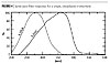
From a practical standpoint, UV sources, especially broad-spectra lamps like medium-pressure mercury lamps and those with additives such as iron or gallium have peaks that fall into these various regions. Figure 1 is a typical spectra of a UV lamp. Formulators ordinarily choose lamp sources that match the UV absorption properties of the photo package (photoinitiator, sensitizers, stabilizers and other materials). These materials have their own absorption spectra, which must coincide with the planned UV source to provide a workable system.
In an ideal world, the UV source would be chosen based on what the formulator requests. In the real world, the formulator often needs to work with an existing UV source that the customer already has or plans to use with a particular formula.
Measuring the individual wavelengths of a few nanometers from a UV source requires a sophisticated instrument called a spectrometer or spectral radiometer. Spectral radiometers, because they can measure individual peaks, can be useful tools for R&D of optical components or new bulb types. For formulators and end users, the output spectra of a UV source is well known. In a production environment, it’s not often practical to make detailed spectral measurements with a spectral radiometer. Simpler devices that measure UV emissions over a broader “band” are more common, affordable, practical and easier to use.
In simple terms, intensity is the output energy of the UV source. Imagine a UV source as though it were the dining room chandelier. More power is applied as the light dimmer is turned up and the visible light output increases. We can also increase the UV output by turning up the “dimmer”. Like a visible bulb, some UV sources have the capability to produce higher intensities than other UV sources. When more power is applied, UV sources generally behave the same way and produce more UV. Doubling the power does not mean that the UV output will double. UV sources are categorized by the amount of applied electrical power to the source. A 300 watt/inch bulb has 300 watts of electrical energy applied for each inch of the bulb. A 300 watt/inch system with a 10” bulb would have 3000 watts of applied power and a 300 watt/system with a 20” bulb would have 6000 watts of applied power.
The applied power does not indicate (a) the amount and type of UV, (b) if the UV is matched to a particular formulation or (c) how much UV is arriving at the cure surface. The amount of UV arriving at the cure surface is called the irradiance. A square centimeter is the area that is used to track arriving UV from all arriving angles and it is generally determined by direct measurement. In theory we always like to measure at the cure surface. In the lab this is generally easier than the realities of measurement in the real world on process equipment.
In the real world the terms intensity and irradiance are sometimes used interchangeably, but from a scientific standpoint irradiance is the UV arriving at a particular (cure) surface based on a specified area – in our case of a square centimeter (cm2).
How and where to measure irradiance is important. Many UV lamps have reflectors to either focus or diffuse their UV energy. UV output may vary depending on the geometry of these reflectors and whether the lamp’s energy is concentrated to one area (focused) or whether it is diffused (non-focused), and will typically also fall off significantly at the ends of an electrode lamp. If we imagine moving a “light meter” around the space near a UV lamp, the needle will jump around as we move the meter. Because of this variation it might be most informative to record the maximum value we measure; this “peak irradiance” is a value that conveys some meaningful information otherwise hard to communicate. Peak irradiance, usually specified as having been measured at a specified distance from the light source, is therefore a common expression of lamp output.
As you might imagine, thinking back to the chandelier analogy, a number of factors affect peak intensity and irradiance: the output of the lamp (how high the dimmer control is “turned up”), the distance to the lamp, and the angle that the incident light strikes the meter.
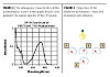
Figure 3 depicts a simple scenario, where the lamp output is maintained at some constant level and the meter is moved from position 1 to position 2, then 3 and 4; the meter responds appropriately. The meter rises as it is moved into the direct path of the light source, and then falls off again as it moved to the other side. It also falls off as the distance increases from position 2 to 3. We know that as we move away from the light source, the measured irradiance decreases. The irradiance will decrease as the square of the distance; move the measurement point twice as far away and we would expect the irradiance to decrease by 1/4th (22= 4, therefore power decreases by 1/4th).
Irradiance measurements, and more commonly Peak Irradiance, is customarily expressed in the units of Watts/cm2 or mW/cm2. Typical industrial UV sources output less than 100 mW/cm2 of UVA to over 5,000 mW/cm2 (5 W/cm2) of UVA.
Irradiance is often viewed as the “punching power” behind UV curing. Irradiance (assuming the proper wavelength) provides the needed energy to penetrate thicker coating films needed to achieve a full depth of cure. And while for some applications, inadequate irradiance will prohibit complete curing, for many applications irradiance and energy density work together to provide an optimum curing profile.
UV Energy Density
Energy density factors in the time factor of the UV exposure. One watt for one second equals one Joule. Energy density is expressed in terms of Joules (or mJ) per cm2. In an ideal world, the product being cured would be exposed to the UV in a ‘square’ or constant irradiance level. An exposure in which the UV source is on, the product is static and a shutter opens and closes for a set time approximates a ‘square’ exposure profile. The energy density could be approximated if the irradiance is known as well as the time of exposure. A surface exposed to a ‘square’ UV source with a peak irradiance of 750 mW/cm2 for 3 seconds receives an energy density reading of 3 x 750 or 2,250 mJ/cm2 (2.25 J/cm2). The majority of exposures in the real world are not ‘square’ exposures. Either the product moves under the lamp or the lamp moves over the product. With changing irradiance levels, we must rely on a radiometer to measure the exposure and then calculate the total energy density.
Energy density is important for the total cure of the material and historically it has been the most common “UV value” shared with end users by formulators. It does not always tell the entire picture.
A note on the “D” (Dose) word: In the real world the word “dose” is often used in place of the term ‘energy density’ or ‘radiant energy density’. In the UV curing world, energy density is a better term, but be aware of customers that may use either term. Decide as a company on what you will use and be consistent with your terminology. We have tried to stick with energy density in this article.
To understand how irradiance and energy density differ, and their respective roles in UV curing, consider the example of cooking some microwave popcorn. The directions on the bag of our Orville Reddenbacker® may recommend that we microwave it for 3 minutes at a high setting. If we use the microwave at its lowest power setting, how long until the popcorn is done? Maybe never. Why? For popping corn the microwave intensity (irradiance) needs to exceed a certain threshold. This is common for popcorn (as well as baking cakes or roasting Thanksgiving turkeys). When roasting a turkey, turning the oven up to 1500 ºF instead of 375 ºF does not ensure a golden brown bird in a short time either. So, too, there is a limit to the beneficial effect of increased irradiance. As we know from our popcorn experience however, time also plays a critical role in the process. Turn off the microwave too early and there are likely to be a cluster of un-popped kernels on the bottom of the bag. We cannot assume that while there is a direct and linear relationship between the mathematics of irradiance and energy density that this means that materials will cure proportionately. While this may hold true for a narrow process window, it is likely to break down at extremes.
Determine how many Joules are needed to cure a particular formulation and application under an UV source in the lab. Take a second sample and leave it outside in the sun for an equivalent Joule exposure. Chances are the properties of the sample left in the sun are different because the UV irradiance was much lower.
In summary, since wavelength is determined by the type of lamp selected (and not a common measurement requirement), specifying the optimum peak irradiance (W/cm2) and energy density (J/cm2) remain the two critical recipe variables needed to produce the perfect UV turkey or popcorn. That said, there are a number of factors that can affect these measurements and introduce potential sources for errors as well.
Irradiance Measurement - Understand Your Instrument
Understanding your UV instruments and their proper use and limits will help both you and your customers to better understand their readings. What factors exist that can cause potential confusion and measurement errors? Are the factors a result of the instrument limits, misuse by the customers or unrealistic expectations? Some of these factors are caused by the limits of the UV measuring device, and some by the measurement procedure, but in any case, being aware of these issues may avoid recording or reporting incorrect or misleading data.Band-Pass Filtering and Attenuation
In engineering detector circuits, it’s a common practice for engineers to use band-pass filters to prevent extraneous signals from interfering with measurement in the desired band, and to maximize the sensitivity of these circuits. An everyday example of band pass filtering is in the circuitry of telephones and other audio devices. For optimal human hearing, telephones reproduce sound from 200 cycles to 20,000 cycles (Hertz). How does this relate to UV? For the wide spectrum of UV, it is convenient to subdivide measurements by band; UVA, UVB, UVC and visible UVV. This division makes it possible to get more precise measurements within each band. But the problem is that each “channel” uses a band-pass filter that can attenuate measurements at extreme ends of the band. The advantage of individual filters is that within each band, sensitivity is improved, but the downside is not being able to steer clear of the edges of the band-pass envelope.
Problems related to filtering do arise. For instance, the development of UV LED light sources with narrow, single wavelength output right near 395 nm is not ideally suited to some of the exisiting filters since the spectral response of the current filters is low in this area where LED output is strong. New filters are now being developed to address this situation.
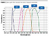
There are differences in the bandwidths between different manufacturers. Each manufacturer selects the optical response components based on their product/instrument design. For the user, this means that readings taken with one brand of radiometer will be different from another even under the exact same conditions. For example, while one EIT radiometer measures UVA with a filter ranging from 320 - 390 nm, another brand uses a broad 250 - 415 nm filter. Readings taken with these two devices will differ. In fact, slight variations from model to model and even device to device are common as manufacturers need to balance the performance of the optics with the cost. Manufacturing of optical components has gotten much better, but it is still normal to have slight variations between optics and/or batches. Eliminating these slight variations would drive the cost of the instrument up significantly.

Cosine Error
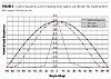
Most radiometers try to replicate a cosine response. Why? It is thought/assumed that UV-cured coatings behave in a cosine manner and that the UV arriving at 90º has the potential to provide more ‘cure’ power than UV arriving at 45º or some other angle. In theory the ‘cure’ power decreases by a component proportional to the cosine of the angle on incidence. For example, as shown in Figure 7, at a 45° angle, the reading is decreased by Cos(45) or 0.707 times the maximum reading. This cosine component is an ideal condition and the optics of the radiometer try to match this response.
Dynamic Range/Solarization of Optics
Weighing a newborn baby on a truck scale would not result in a very accurate measurement because the truck scale is set up for much higher weights. Be sure to also select a radiometer with the proper scale for your measurements. Using an instrument geared for high (power)-intensity measurements on a low-intensity (power) source will produce the same results as the truck scale example. Using an instrument that was designed for low (power)-intensity sources on a high (power)-intensity source will more than likely damage the instrument.
Radiometers rely on small electronic detectors for measurement and a number of optical components to condition the incoming UV energy. The instrument needs to balance between the amount of UV reaching the detector. Enough UV needs to reach the detector so that it can generate a proper signal, but too much UV has the potential to damage the optics through the process of solarization. Some components, when exposed continuously to high levels of UV can deteriorate, or ‘solarize’ with age. Solarization typically changes the transmission properties of the materials and affects accurate measurement by attenuating, or decreasing UV measurements over time. While the solarization process can be minimized by choosing superior materials, it is unfortunately often unavoidable. Periodic calibration can compensate for minor change and long term some optical components may need to be replaced.
Temperature
Process heat is the unwanted, but often unavoidable, byproduct of UV curing. Many UV lamps radiate more energy in the long wavelength infrared and convection portion of the spectrum than they do in the UV region. And while UV radiometers may not be measuring this energy, they can be affected by it and the heat in the process may unknowingly introduce UV measurement error, especially on long exposures of very high power sources. Check with your supplier to see how the detector on their instrument responds. The response of many detectors will cause the readings to drop slightly.
Extreme temperatures can even damage some instruments; in general, “if it’s too hot to touch – it’s too hot to measure.” Some radiometers provide a convenient display of internal temperature so that this can be recorded in the lab notebook, and an internal alarm that will warn if the internal temperature exceeds a recommended operating temperature (say 65 ºC).
Writing A UV Specification
One of the most common and important uses of good measurement practices for suppliers is developing curing specifications. Hopefully the preceding discussion shed some light on what is important in a good specification. Wavelength, irradiance and energy density are all important to the process and should be part of a well crafted specification.While there is frequently a need to protect proprietary information, the curing specification should be viewed as a communications tool and as a starting point for your customers to optimize their process.
It’s not enough to describe the UV source since source output can (and does) change over time, and because not all customers will choose to use the specified source. So, while testing may be done with a 300 W/in Fusion H lamp, or a 200 W/in iron additive lamp, this description is not a substitute for a specification.
Some examples of UV specifications are as follows.
Fusion 600 W/in Lamp
This is a poor description. There’s too little information to do much of anything here. 600 W/in is a measure of the power that goes into this lamp and does not give any information about the UV at the part. Which wavelength? H, V, D lamp? What about energy density?
400 W/in Mercury Arc Lamp for 5 Seconds
This is a little better, but there is still more information about the light source than about UV reaching the part. What we want to see is some irradiance or dose measurement information.
600 mJ/cm2
Better again; at least there’s now some measurement information. But a good deal of important data is still left out, for example at what wavelength?
600 mJ/cm2 UVA
A good specification. There’s enough here to replicate this specification if we only knew what measuring tool to use.
600 mJ/cm2 UVA (EIT 320-390)
A better specification. We can tell what type of radiometer was used to measure this data.
300 mW/cm2 600 mJ/cm2 UVA (EIT 320-390)
Best. There’s a complete set of information to help ensure proper cure and how to replicate the laboratory conditions in the field.
For some coating processes, two lamps are required to achieve complete cure of both the surface and through cure. This should be described with appropriate data and curing information. In all cases, additional information such as the UV bulb type as well as coating thickness and application data will help customers understand your intentions, and provide a more complete guideline to help them establish and maintain a proper process. This up-front communication helps to eliminate costly finger-pointing mistakes down the road.
Summary
End users rely on UV measurement to monitor their process, and to troubleshoot when things go wrong. But suppliers often need to help establish these specifications. Like any specification process, clear communication is essential to ensure that the recipient of the information clearly understands what the provider intends. To that extent, a specification that includes the basic elements needed to replicate the process is needed.We have seen that UV measurement includes a description related to wavelength, irradiance (typically peak irradiance) and energy density (dose). In Part I we looked at some factors that can influence irradiance measurements such as filtering, solarization and cosine error. Part II will examine some factors that can influence energy density, how reflectors influence measurements and how to select a radiometer for laboratory work.
For more information, contact pmillsoh@aol.com or see www.uvrobtics.com.
Looking for a reprint of this article?
From high-res PDFs to custom plaques, order your copy today!


