Interference Pigments
Interference pigments are employed in many automotive and industrial paint formulations. Their high popularity is due to their fascinating interplay of color and to effects due to the various materials employed in their layered structures. Refractions and reflections of light at, and within, those layers cause interferences yielding selected colors.
Classification
Interference pigments may be classified by either the method employed for their manufacture or by their structure. Substances, such as titanium dioxide or iron oxide, that have high indices of refraction, may, for example, be deposited on a transparent substrate, such as mica in the case of Iriodin, silicon dioxide in the case of Colorstream, or aluminum oxide in the case of Xirallic. Such pigments are produced using wet-chemical processes, while those having an aluminum layer as an internal reflector (Variochrom, ChromaFlair and SpectraFlair) are manufactured in high vacuum. Liquid crystals are also classed as interference pigments.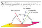
Angular Relationships of Metrological Setups
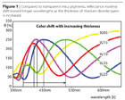
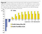
Interference pigments manipulate incident light by means of refractions and reflections such that the resultant refracted and reflected light generates color perceptions in the human eye and brain. That refracted and reflected light is selectively affected by two major factors. First, the thicknesses of their layers and the materials constituting the latter determine their “base colors”. For example, depositing layers of titanium dioxide having different thicknesses on a mica plate yields silvery-white, yellow, red, blue or green.The reflectance curves of such pigments for a particular geometry, e.g., 45°/120° (illumination/observing), exhibit a readily discernible shift in their respective reflectance maxima toward longer wavelengths. The reflectance minimum of the silvery-white pigment will be shifted from the UV to the blue spectral range as layer thicknesses increase, while, in this particular case, the plateau of its reflectance maximum spans the green, yellow and red spectral ranges and leads to a gold-yellow color. Further increases in layer thickness will shift that plateau toward even longer wavelengths, and simultaneously shift the next reflectance maximum from the UV to the blue-violet spectral range. The latter maximum will then be responsible for its blue color, as well as the green color that arises when the thickness of its layers is further increased, when viewed at the angle of specular reflection. The ostensibly unusual ordering, yellow, red, blue and green, of colors for increasing thickness of the layers of titanium dioxide is thus due to its reflectance maxima being shifted toward longer wavelengths. (Figure 1)
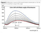
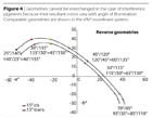
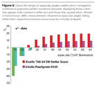
The second factor involved is attributable to one of the key features of interference pigments. Optic laws dictate that their reflectance maximum will be shifted toward shorter wavelengths as the angle of illumination is varied from steep, near-normal incidence to flat, near-grazing incidence. That key feature is peculiar to the particular pigment involved, and thus may be used for its characterization and identification. (Figure 2)
If these particular optical properties of interference pigments are to be utilized for their visual and instrumental assessment, the first thing that will be necessary is to address the matter of geometries to be employed. If a semicircle graduated from 0° to 180° inclusive, is set upright on the test panel, practical considerations dictate that the angle of illumination should range from 0° to 90° and that the associated angles of specular reflection should range from 90° to 180°. For example, if the angle of illumination is 60°, the angle of specular reflection will be 120°, i.e., the angles of illumination and specular reflection will be displaced + 30° and – 30° from the local normal to the surface, respectively. Since measurements will be made at angles differing from the angle of specular reflection, another factor needed for specifying the geometries involved will be the aspecular angle, i.e., the difference between the angle of specular reflection and the angle of observation. For example, if, in the case of the example mentioned above, measurements are made at 105°, the aspecular angle will be 15°. (Figure 3)
The resultant colors exhibited by interference pigments vary with the geometries involved, which is why accurate definitions of, and accurate statements respecting, the latter are essential. Defining the angles involved utilizing the semicircle method will greatly simplify comprehension of particular situations. Although stating the angles of illumination and observation as 45° and 120°, respectively, is unambiguous, an aspecular angle of 15° may occur for various angles of illumination, which is why one should not allow themselves to become confused by statements confined to the difference in the angles of specular reflection and observation.
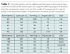
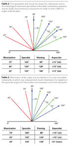
Two examples will indicate that comparable angular relationships will not necessarily occur in such cases. In the case of the first example, measurements are made at 120°, 110°, 90°, 60° and 25° for a constant 45° angle of illumination. The respective aspecular angles involved will then be 15°, 25°, 45°, 75° and 110°, referred to the 135° angle of specular reflection. In this particular case, all measurements are taken from the cis-side, i.e., from the same side of the specular reflection as the incident illumination.
In the case of the second example, observation is at a constant 45°, and the angle of illumination is initially 120°. The associated angle of specular reflection will then be 60°, which yields a difference of 15° in the angles of specular reflection and observation. However, in this case, observation will be from the trans-side, i.e., from the opposite side of the specular reflection, referred to the incident illumination. Subsequent geometries cover angles of illumination of 110°, 90°, 60° and 25°. At angles of illumination of 60° and 25° the angles of specular reflection will be 120° and 155°, respectively. In both of those cases, the angles of observation will be on the cis-side as shown in Table 1.
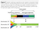
However, measurements on interference pigments clearly indicate that the results of measurements made from the cis-side and the trans-side will differ, which is why distinguishing between them is essential. Although the absolute values of the aspecular angles involved may be identical, the respective, associated angles of illumination and observation indicate that no comparisons can be made for any, given, angular relationship. If, for example, the angle of illumination is 45° and the angle of observation is 110°, the aspecular angle will be 25°. Although an angle of illumination of 110° and an angle of observation of 45° would yield the same aspecular angle, observation would be from the trans-side, and, since the colors exhibited by interference pigments vary with the angle at which they are illuminated, no comparisons of measurements made at 110° and 45° are possible for the same aspecular angle. (Figure 4)
Choosing the Geometries
The geometries needed for evaluating and observing interference pigments may be derived from their interference properties. Paints containing interference pigments are usually treated in the same manner as metallic paints. Measurements are made at specified angular intervals, referred to the angle of specular reflection, which yields a series of measured spectral data. Analyses of data acquired for three or four aspecular angles are frequently regarded as sufficient, although they cover, and employ, merely a fraction of the colorimetric data available. Since the color shift toward shorter wavelengths is a property peculiar to the interference pigment involved, it should be employed in visually and instrumentally characterizing interference pigments.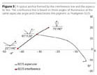
In the case of steeper angles of illumination, illumination at 70° or 75° has been found to be the best choice, since, firstly, the differences between measurement results obtained for the two choices will be slight, and, secondly, employing a steeper angle of illumination might be impossible due to limitations imposed by the setup employed.
For an angle of illumination of 75° and an aspecular angle of 15°, measurements will be made at 90°. However, the light source and detector head might interfere with one another for smaller aspecular angles. Furthermore, at an angle of illumination of 75°, the observation angle will be identical to that for an angle of illumination of 45°, since the aspecular angle, 45°, will be identical to the 15° aspecular angle employed in the case of a 75° angle of illumination.
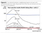
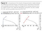
When considering suitable choices of metrological geometries, there arises the question of how close to the angle of specular reflection measurements can, and should, be made. Based on my personal experience, it may be stated that a minimum displacement of 15° will be sufficient, as well as present no problems due to artifacts. Measurements made at aspecular angles less than 10° frequently exhibit irregularities and disagreements, particularly in the case of samples overcoated with clear lacquers. According to the laws of physics, the intervals between maxima will increase as the angle of observation approaches the angle of specular reflection. If the intervals between maxima for aspecular angles of 10° and 15° should be less than those for aspecular angles of 15° and 20°, the decreases observed will most likely be artifacts. (Figure 6)
If transparent interference pigments (Iriodin or Xirallic), or similarly formulated paints, are applied to a white background, the proportion of interference pigment involved may be determined from the overall impression of the color it yields. (Figure 7) The color that it exhibits when viewed in and near reflected light will change to the respective complementary transmission color when the aspecular angle is 25° or 30°. For example, at an aspecular angle of 15°, the blue color reflected by the outer surface of the pigment will be observed.
Measurements made at various angles of illumination for the same aspecular angle yield an interference line that is peculiar to the particular interference pigment involved. Measurements made at a constant angle of illumination, e.g., 45°, for various angles of observation and aspecular angles yield an aspecular line. Together, those two lines resemble an anchor, where neither is necessarily a straight line. Particularly “traveler” pigments, which exhibit much more extensive color changes than so-called “shifter” pigments, may exhibit highly complex interference lines. Although aspecular lines usually all have a uniform shape, they might well extend over several quadrants of the a*b*-coordinate system in the case of diffraction pigments.
Employment of the Geometries Involved
Several of the numerous, feasible, metrological setups have been found to be at least essential for measuring interference pigments and paints pigmented with them. (Tables 2, 3) As mentioned above, the interference lines of the pigments involved reflect their optical properties. Their interference lines are often curved, which is why at least three data points obtained for differing angles of illumination will be necessary for defining them. (Figure 10) Since another three or four data points will be needed for defining their aspecular lines, the optical properties of interference pigments may be adequately described using measurements obtained for a total of five or six geometries, where it should not be forgotten that the choice of the angles to be involved, e.g., illumination at 45°, is both arbitrary and dependent upon the designs of the instrumentation to be employed. The matter of whether the results obtained agree with visual assessments conducted in front of windows or in light booths is initially ignored.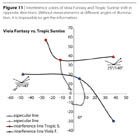
Discussion of the Application Areas Involved
Multi-angle spectrophotometers that employ either a fixed angle of illumination and several angles of observation, or vice versa, are currently employed for measuring the properties of interference pigments. Data obtained for at most three, and sometimes just two, of the various, feasible, geometries is taken into account in the subsequent analyses. The application areas range from the automotive and manufacturing industries, through the paint-manufacturing industry, to the pigment-manufacturing industry. Additional geometries are employed in all industries that utilize either interference pigments or paints pigmented with them.In general, interference measurements allow determining the optical properties of interference pigments. They also yield key representations of the courses of color curves in the a*b*-coordinate system. Distinguishing between two pigments, such as Viola Fantasy, whose color varies from red-violet, through yellow, to green and Tropic Sunrise, whose color varies over the same spectral range, but in the reverse order, would be impossible without such measurements. (Figure 11) In the case of refinishing operations and OEMs, unknown paint formulations may be determined much faster, more simply, and more reliably utilizing the results of interference measurements. Every interference pigment has a unique “fingerprint” ascribable to measurements conducted for various angles of illumination at a constant aspecular angle.
Since overall impressions of the colors exhibited by interference pigments consist of several components, admixture formulations may be devised more rapidly, and thus at lower cost. In many cases, the total numbers of paint admixtures required and constituents of paint formulations may be reduced if both the interference and absorption contributions are measured employing this “holistic” method.
Looking for a reprint of this article?
From high-res PDFs to custom plaques, order your copy today!


