Painting & Coating Industry (PCI) logo Powder coating summit logo
  • Sign In
  • Create Account
  • Sign Out
  • My Account
  • NEWS
  • PRODUCTS
  • MATERIALS
  • TECHNOLOGIES
  • FINISHING
  • RESOURCES
  • EVENTS
  • DIRECTORIES
  • EMAGAZINE
  • CONTACT
cart
facebook twitter linkedin youtube
  • NEWS
  • Latest News
  • Market Trends & Reports
  • Price Alerts
  • Subscribe to eNewsletters
  • Global Top 10/ PCI 25
  • Weekly Featured Article
  • COATLE Word Game
  • PRODUCTS
  • Product News
  • Must See Products and Services
  • MATERIALS
  • Additives
  • Resins/Polymers
  • Pigments
  • Equipment
  • Distributors
  • TECHNOLOGIES
  • Adhesives
  • Architectural Coatings
  • Industrial Coatings
  • Nanotechnology
  • Powder Coatings
  • Solventborne
  • Special Purpose Coatings
  • Sustainability
  • UV Coatings
  • Waterborne
  • Waterborne
  • FINISHING
  • Finishing News
  • Finishing Technologies
  • Finishing Equipment
  • RESOURCES
  • Columns
  • Blogs
  • Coatings Supplier Handbook
  • Podcasts and Videos
  • PCI Store
  • eBooks
  • Sponsor Insights
  • White Papers
  • COATLE Word Game
  • Columns
  • Ask Joe Powder
  • Did you know?
  • Distribution Dive
  • Focus on Canada
  • Formulating With Mike
  • Innovation Insights
  • Moody's Coatings Conundrums
  • Powder Coating Perspectives
  • Target the Market
  • TiO2 Insider
  • Blogs
  • Editor's Viewpoint
  • Industry Insights
  • Podcasts and Videos
  • COAT-IT! Podcast
  • Videos/PCI TV
  • EVENTS
  • Coatings Trends & Technologies Summit
  • Paint and Coatings Academy
  • Webinars
  • Calendar of Events
  • Lifetime Achievement Award
  • DIRECTORIES
  • Buyer's Guide
  • Equipment Directory
  • Materials Directory
  • EMAGAZINE
  • Current Issue
  • eMagazine Archive
  • China Issue Archive
  • Editorial Advisory Board
  • CONTACT
  • Contact Us
  • Advertise
  • Subscribe to eMagazine
  • Subscribe to eNewsletters
Painting & Coating Industry (PCI) logo Powder coating summit logo
search
cart
facebook twitter linkedin youtube
  • Sign In
  • Create Account
  • Sign Out
  • My Account
Painting & Coating Industry (PCI) logo Powder coating summit logo
  • NEWS
    • Latest News
    • Market Trends & Reports
    • Price Alerts
    • Subscribe to eNewsletters
    • Global Top 10/ PCI 25
    • Weekly Featured Article
    • COATLE Word Game
  • PRODUCTS
    • Product News
    • Must See Products and Services
  • MATERIALS
    • Additives
    • Resins/Polymers
    • Pigments
    • Equipment
    • Distributors
  • TECHNOLOGIES
    • Adhesives
    • Architectural Coatings
    • Industrial Coatings
    • Nanotechnology
    • Powder Coatings
    • Solventborne
    • Special Purpose Coatings
    • Sustainability
    • UV Coatings
    • Waterborne
    • FINISHING
      • Finishing News
      • Finishing Technologies
      • Finishing Equipment
    • RESOURCES
      • Columns
        • Ask Joe Powder
        • Did you know?
        • Distribution Dive
        • Focus on Canada
        • Formulating With Mike
        • Innovation Insights
        • Moody's Coatings Conundrums
        • Powder Coating Perspectives
        • Target the Market
        • TiO2 Insider
      • Blogs
        • Editor's Viewpoint
        • Industry Insights
      • Coatings Supplier Handbook
      • Podcasts and Videos
        • COAT-IT! Podcast
        • Videos/PCI TV
      • PCI Store
      • eBooks
      • Sponsor Insights
      • White Papers
      • COATLE Word Game
    • EVENTS
      • Coatings Trends & Technologies Summit
      • Paint and Coatings Academy
      • Webinars
      • Calendar of Events
      • Lifetime Achievement Award
    • DIRECTORIES
      • Buyer's Guide
      • Equipment Directory
      • Materials Directory
    • EMAGAZINE
      • Current Issue
      • eMagazine Archive
      • China Issue Archive
      • Editorial Advisory Board
    • CONTACT
      • Contact Us
      • Advertise
      • Subscribe to eMagazine
      • Subscribe to eNewsletters

    Man versus Machine

    By Werner Rudolf Cramer
    September 1, 2006
    Figure 1. Click image for larger view.
    The objective of colorimetry is arriving at a characterization of color and color fidelity that is as objective as possible. It is supposed to generate the linkages between physical measurements and physiological sensory stimuli, independent of any subjective factors. The fact that purely visual judgments yield results differing from instrumental characterizations, particularly in the case of interference pigments, is due to differing circumstances, rather than the nature of the subject matter.

    Regardless of whether one works in the pigment, paint or automotive industry, those who deal with interference pigments cannot avoid contending with their physical and optical properties. Unfortunately, that is frequently forgotten and ignored due to a lack of knowledge of, and experience with, that particular type of pigment. Visual and instrumental characterization of a pigment's optical properties are equally important, since the color that results will vary with the angle at which light is incident on it. Together with the viewing angle, that angle yields a precise representation of the interferences involved.


    Figure 2. Click image for larger view.
    Measurements on a pigment that are made while varying the incidence from a flat angle at 25°, through the conventional at 45° to a steep angle at 75°, while maintaining a constant 15° difference between the respective angles of specular reflection and viewing, yield a characteristic interference line for that particular pigment and angular difference (Figure 1). The designations of angles employed here are referred to a graduated semicircular arc covering the angular range 0°-180° residing atop a test panel, where the plane of the arc is normal to the surface of the test panel, in which case, the normal to the panel's surface will coincide with 90°. Illumination at 45° will yield a specular reflection at 135° (cf. the endnotes). The measurement results for any other angle of illumination will be stable and plausible, provided that the difference between the angle of specular reflection and the viewing angle remains constant at 15°. Employing lesser differences in those angles could cause discrepancies to arise, particularly in the case of basecoat/clearcoat systems. Employing greater differences in them could cause light scattered by interference pigments, and admixtures pigmented with them, to be included in the results obtained.


    Figure 3. Click image for larger view.
    Interference pigments generally exhibit a shift in their reflectance maxima toward shorter wavelengths when illuminated at flatter angles. For example, the reflectance peak of a conventional pearl-green pigment will be shifted from the yellow-green to the blue-green spectral range, while that of a red pigment will be shifted from the blue-red to the yellow spectral range (Figure 2). Those statements apply to both the pigments alone and their admixtures with both colored and aluminum pigments. The method involving varying the angle of illumination while maintaining a constant difference between the angle of specular reflection and the viewing angle thus provides ideal means for identifying and characterizing interference pigments. Every interference pigment has its own individual set of optical properties that it retains, even in admixtures.

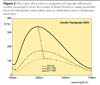
    Geometries other than that mentioned above, including those where the angle of illumination is held constant and the difference between the angle of specular reflection and the viewing angle is varied, are employed in arriving at complete characterizations of the optical properties of interference pigments. The results of such measurements yield aspecular lines that are largely attributable to scattered light and characteristic of the particular angle of illumination employed. Illumination is usually at 45°, and measurements are taken while the difference between the angle of specular reflection and the viewing angle is varied from 15° to 25°, 45°, 75° and 110° (aspecular angle).

    Such geometries are currently employed in industry, although interferences cannot be acquired for the reasons stated above, where various interference pigments or admixtures of them with other pigments may well yield nearly identical aspecular lines (Figure 3). Delivery conditions thus cannot be formulated based on such measurements in the case of interference pigments and paints pigmented with them.


    Figure 4. Click image for larger view.

    Visual Characterizations

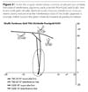
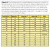
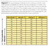
    In the case of visual inspections, inspectors normally stand opposite a laboratory window and point a test panel at the window. They initiate their inspections by holding a test panel flat against their stomach or chest such that they see light from the window reflected in the panel. Without shifting their location, they then tilt the panel upward or downward. If we examine the metrological geometries for those motions, we arrive at the following procedure for checking test samples.

    At its initial orientation, the test panel will be illuminated at an angle of incidence of 75° and viewed at an angle of 105°, the angle at which light coming from outdoors will be specularly reflected by the test panel. If the panel is then tilted downward 5°, the angle of illumination will change from 75° to 80°, the angle of specular reflection will change from 105° to 100°, and the viewing angle will change from 105° to 110°. The angular relationships between the illumination (light coming from outdoors), the observer (the inspector's eyes) and the plane of the sample undergoing testing will then have changed. For the case in question, the difference angle will become -10°, i.e., viewing will be from a trans-location. Viewing will then take place from the far side of the specularly reflected beam, referred to the incident (trans-side) illumination.

    Continuing to tilt the test panel downward in 5° increments will increase the angle of incidence from 80° to 85° and 90°. The angle of specular reflection will then change from 100° to 95° and 90°, respectively; the viewing angle will change from 110° to 115° and 120°, respectively, and their difference will change from -10° to -20° and -30°, respectively (Figure 4).


    Figure 5. Click image for larger view.
    The next 5° increment will shift the angle of illumination to the other side of the normal to the panel's surface, i.e., increase it to 95°. The angle of specular reflection will then be 85°, while the viewing angle will increase to 125°. The difference between the latter two angles will have meanwhile become 40°, and viewing will have shifted to a cis-location. Viewing will then be from the same side of the normal to the panel's surface as the incident (cis-side) illumination. Viewing will continue to be from the cis-side for further increments in the angle of illumination. Shifts from the trans-side to the cis-side, and vice versa, will yield differing measurement results for the same absolute values of the difference in the angle of specular reflection and the viewing angle. This is why such measurement results should not be compared.

    Similar relationships occur when the test panel is tilted upward, i.e., in this case, the angles of illumination, viewing and the difference between the angle of specular reflection and the viewing angle will simultaneously vary (Figure 5). These geometries, which occur when visually characterizing samples while standing opposite a laboratory window, never occur in the case of commercially available photometric instrumentation, which is why agreement between visual and instrumental characterizations of interference pigments will never occur.


    Figure 6. Click image for larger view.

    Light Booth

    There are two methods for characterizing test panels in a light booth. Either the test panel involved is tilted in one direction or the other, without establishing the angular relationships to be involved, as in the case of visual characterizations, or the test panel is placed on a mechanism situated in the illumination chamber that predetermines certain angular relationships. Illumination is vertically from above in either case. Such mechanisms usually presume an angular relationship for which the viewer will see the light source reflected in the test panel, but take no account of the viewer's height and distance from the test panel, i.e., take no account of the viewing location.

    Assuming that the test panel is inclined at an angle of 20° with respect to the laboratory table, we arrive at the following angular relationships, referred to the plane of the test panel. The angle of illumination will be 70°, and the viewer will see the light source reflected in the panel when viewing it at an angle of 110°. The test panel is then tilted upward and downward through 10°, yielding the following angular relationships. The angle of illumination will change from 70° to 80°, and the angle of specular reflection will become 100°. Viewing will then be at a trans difference between the angle of specular reflection and the viewing angle of -20°. Similarly, tilting the test panel in the other direction through 10° will yield a cis difference angle of +20°. The viewing angle will change from 70° to 60°, the angle of specular reflection will become 120° and the viewing angle will become 100°. No such angular relationships are implemented in any items of photometric instrumentation.

    In the case of "uncontrolled" motions of a test panel, it is presumed that the incident light beam is perpendicular to the plane of the panel. Viewing will then be at an angle of, for example, 135°, depending upon the viewer's height, their distance from the test panel, and the location of their eyes. If the test panel is then tilted through 5° toward the viewer, the angle of illumination will change from 90° to 85°, the angle of specular reflection will change from 90° to 95° and the viewing angle will change from 135° to 140°, yielding a cis aspecular angle of 40°. Continuing to tilt the test panel toward the viewer will increase all of the angles involved (Figure 6).


    Figure 7. Click image for larger view.
    If the test panel is tilted in the opposite direction, i.e., away from the viewer, both the angle of illumination and the viewing angle will decrease and the angle of specular reflection will be correspondingly increased. The included angle between the specular reflection and the viewing angle will initially be at a trans location and transit to a cis location when the angle of illumination changes from 70° to 65°. As in the cases of the angular relationships for "controlled" viewing in a light booth and those for viewing opposite a window, the angular relationships that apply here have not been implemented in any commercially available photometric instrumentation (Figure 7), which is why no comparisons of visual and instrumental characterization of interference pigments can be made. That fact frequently leads to wrong decisions when assessing colors and differences in colors.

    However, there is a method for visually characterizing interference pigments and admixtures pigmented with interference pigments that overlaps instrumental characterizations. The optical properties of interference pigments may be acquired if the angle of illumination is varied while the aspecular angle, i.e., the difference between the angle of specular reflection and the viewing angle, is held constant. When illumination and reflection are at steep angles, measurements are made at angles close to the angle of specular reflection.


    Figure 8. Click image for larger view.
    In the case of flat angles, measurements are also made at angles close to the angle of specular reflection. Visual characterization involves laying a test panel flat on the palm of one's hand and extending the arm involved toward a light source such that grazing incidence results. One then alters the test panel's location by translating it downward, while keeping it parallel to its original orientation, keeping the arm involved outstretched and simultaneously walking toward the light source in order to allow the light source to illuminate the test panel at steeper angles of incidence. The important factor here is the parallel translation of the test panel necessary in order to maintain a constant difference between the angle of specular reflection and the viewing angle (Figure 8). The colors observed will then agree with instrumental characterizations.

    Interference pigments, such as Iriodin Pearl Gold and the similarly formulated Xirallic Sunbeam Gold, may also be distinguished using this visual method. However, conventional visual and instrumental methods yield hardly any differences between those pigments.


    Figure 9. Click image for larger view.

    The Effects of Solar Altitude

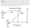
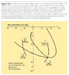
    When assessing interference colors in vivo on a vehicle, some of the factors that must be taken into account are the current solar altitude, the viewer's height and the viewer's distance from the vehicle. In conjunction with the solar altitude, yet another factor that plays a role is the geographic latitude of the viewing site involved. If we ignore spectral and intensity shifts due to the Rayleigh and Tyndall effects and assume uniformly white sunlight, we arrive at two types of examples having differing sets of parameters.

    Münster, Germany, which is situated at 52° north latitude, has a lot of rain and few sunny days. Fort Lauderdale, Florida is situated at 26° north latitude, has little rain and many sunny days. It is assumed that the viewer is situated at the same location opposite the vehicle's left-front wheel and looking at its hood. The sun is shining on the opposite side of the vehicle such that sunlight is reflected off its hood, toward the viewer. At noon in Münster in mid June, the solar altitude (90°, minus Münster's latitude, plus the solar declination) will be its annual maximum of 61°. The viewer will perceive the resultant interference color occurring close to the specular reflection (Figure 9). Although a viewer situated at the same location with respect to the same vehicle in Fort Lauderdale, where it will be earlier in the morning, will perceive the same color as the viewer in Münster, it will have changed when noon rolls around, since the solar altitude will have increased to 81°. The interference colors occurring between those two solar altitudes cannot be observed in Münster, since the solar altitude there never exceeds 61° (Figure 10).


    Figure 10. Click image for larger view.
    Although this example should not be construed as an appeal for new methods and alternative conditions for characterizing the colors of interference pigments, it indicates how drastic the effects of angle of illumination on resultant interference colors can be. In any event, the proposed method for visually and instrumentally characterizing interference pigments using various angles of illumination is suitable for assessing even extreme in vivo experiences.

    Interference pigments have optical properties that may be acquired using new visual and instrumental methods. Conventional methods provide little information that will allow formulating descriptions of value for incoming-goods inspections and quality control. Conventional methods are also hardly suitable for identification and characterization purposes, which means that expending more time and effort on their identification and characterization and obtaining incorrect results are inevitable. Further work on the optical properties of interference pigments will only benefit all involved.

    Notes

    The various conventions for designating angles in the case of reflectance measurements were discussed by ASTM Working Group E 12.06. In contrast to the standard practice, which associates the normals to surfaces with 0°, the convention employed here superimposes a graduated, semicircular arc covering the angular range 0° - 180° whose plane is normal to the surface whose reflectance is to be measured on that surface, which means that the normal to the surface will be at 90°, rather than 0°. Although that approach yields clearer descriptions of the angular relationships involved in reflectance measurements, it causes purists' hair to stand on end. For more information, e-mail wcramer@muenster.de.

    Share This Story

    Looking for a reprint of this article?
    From high-res PDFs to custom plaques, order your copy today!

    Werner Rudolf Cramer | Muenster, Germany

    Recommended Content

    JOIN TODAY
    to unlock your recommendations.

    Already have an account? Sign In

    • PCI-0724-Global10-Feature-1440.png

      2024 Global Top 10: Top Paint and Coatings Companies

      Who ranks on top? PCI’s annual ranking of the top 10...
      Paint and Coating Market Reports
      By: Courtney Bassett
    • PCI-0724-PCI25-Feature-1440.png

      2024 PCI 25: Top Paint and Coatings Companies

      PCI's annual ranking of the top 25 North American paint...
      Global Top 10 and PCI 25
      By: Courtney Bassett
    • pci1022-Kinaltek-Lead-1170.jpg

      A Novel Pigment Production Technology

      Following an extensive R&D program that demonstrated...
      Paint and Coating Pigments
      By: Jawad Haidar and Nitin Soni
    You must login or register in order to post a comment.

    Report Abusive Comment

    Subscribe For Free!
    • eMagazine
    • eNewsletter
    • Online Registration
    • Subscription Customer Service

    The Coatings Minute: Your Inside Look at PCInnovations

    The Coatings Minute: Your Inside Look at PCInnovations

    The Coatings Minute: Print Returns with PCI’s New Showcase Issue

    The Coatings Minute: Print Returns with PCI’s New Showcase Issue

    CTT Registration Now Open

    CTT Registration Now Open

    The Coatings Minute: Why Industry News Matters More Than Ever

    The Coatings Minute: Why Industry News Matters More Than Ever

    More Videos

    Sponsored Content

    Sponsored Content is a special paid section where industry companies provide high quality, objective, non-commercial content around topics of interest to the PCI audience. All Sponsored Content is supplied by the advertising company and any opinions expressed in this article are those of the author and not necessarily reflect the views of PCI or its parent company, BNP Media. Interested in participating in our Sponsored Content section? Contact your local rep!

    close
    • Modern arapartment complex painted in bright colors.
      Sponsored byEPS - Engineered Polymer Solutions

      Architectural Polymers Leading the Way in Coatings Innovation

    • paint sprayer in a workshop
      Sponsored byallnex

      Enabling Performance and Compliance: allnex Introduces a New Line of VOC Exempt Solvent-Borne Resins

    Popular Stories

    No. 3 AkzoNobel

    AkzoNobel to Close Two Manufacturing Sites

    A collage of products using non-PFAS

    A Surge in Non-PFAS Releases

    Modern living room interior with green plants, sofa and green wall

    Reimagining Architectural Paints with Plant-Based Acrylic Binders


    PCI Buyers Guide

    Submit a Request for Proposal (RFP) to suppliers of your choice with details on what you need with a click of a button

    Start your RFP

    Browse our Buyers Guide for manufacturers and distributors of all types of coatings products and much more!

    Find Suppliers

    Events

    September 3, 2025

    Coatings Trends & Technologies Summit

    The Coatings Trends & Technologies (CTT) Summit is an annual conference for both liquid and powder coatings formulators and manufacturers to discuss innovations in coatings technology. This event combines high-quality technical presentations, a resource-rich exhibit hall, and dedicated networking opportunities to connect scientific minds, foster innovation, and cultivate game-changing new ideas!

    January 1, 2030

    Webinar Sponsorship Information

    For webinar sponsorship information, visit www.bnpevents.com/webinars or email webinars@bnpmedia.com.

    View All Submit An Event

    Poll

    Longest-running laboratory experiment

    What is the longest-running laboratory experiment?
    View Results Poll Archive

    Products

    CTT Summit Short Courses (Live 9/3/25)

    Coatings Trends & Technologies Summit is expanding its offerings with four short courses. These short courses will offer an extensive day of interactive learning.

    See More Products
    pci  webinar april 2025

    PCI CASE EBOOK
    ×

    Keep the info flowing with our eNewsletters!

    Get the latest industry updates tailored your way.

    JOIN TODAY!
    • RESOURCES
      • Advertise
      • Contact Us
      • Directories
      • Store
      • Want More
    • SIGN UP TODAY
      • Create Account
      • eMagazine
      • eNewsletters
      • Customer Service
      • Manage Preferences
    • SERVICES
      • Marketing Services
      • Reprints
      • Market Research
      • List Rental
      • Survey & Sample
    • STAY CONNECTED
      • LinkedIn
      • Facebook
      • Youtube
      • X (Twitter)
    • PRIVACY
      • PRIVACY POLICY
      • TERMS & CONDITIONS
      • DO NOT SELL MY PERSONAL INFORMATION
      • PRIVACY REQUEST
      • ACCESSIBILITY

    Copyright ©2025. All Rights Reserved BNP Media.

    Design, CMS, Hosting & Web Development :: ePublishing

    Painting & Coating Industry (PCI) logo Powder coating summit logo
    search
    cart
    facebook twitter linkedin youtube
    • Sign In
    • Create Account
    • Sign Out
    • My Account
    Painting & Coating Industry (PCI) logo Powder coating summit logo
    • NEWS
      • Latest News
      • Market Trends & Reports
      • Price Alerts
      • Subscribe to eNewsletters
      • Global Top 10/ PCI 25
      • Weekly Featured Article
      • COATLE Word Game
    • PRODUCTS
      • Product News
      • Must See Products and Services
    • MATERIALS
      • Additives
      • Resins/Polymers
      • Pigments
      • Equipment
      • Distributors
    • TECHNOLOGIES
      • Adhesives
      • Architectural Coatings
      • Industrial Coatings
      • Nanotechnology
      • Powder Coatings
      • Solventborne
      • Special Purpose Coatings
      • Sustainability
      • UV Coatings
      • Waterborne
      • FINISHING
        • Finishing News
        • Finishing Technologies
        • Finishing Equipment
      • RESOURCES
        • Columns
          • Ask Joe Powder
          • Did you know?
          • Distribution Dive
          • Focus on Canada
          • Formulating With Mike
          • Innovation Insights
          • Moody's Coatings Conundrums
          • Powder Coating Perspectives
          • Target the Market
          • TiO2 Insider
        • Blogs
          • Editor's Viewpoint
          • Industry Insights
        • Coatings Supplier Handbook
        • Podcasts and Videos
          • COAT-IT! Podcast
          • Videos/PCI TV
        • PCI Store
        • eBooks
        • Sponsor Insights
        • White Papers
        • COATLE Word Game
      • EVENTS
        • Coatings Trends & Technologies Summit
        • Paint and Coatings Academy
        • Webinars
        • Calendar of Events
        • Lifetime Achievement Award
      • DIRECTORIES
        • Buyer's Guide
        • Equipment Directory
        • Materials Directory
      • EMAGAZINE
        • Current Issue
        • eMagazine Archive
        • China Issue Archive
        • Editorial Advisory Board
      • CONTACT
        • Contact Us
        • Advertise
        • Subscribe to eMagazine
        • Subscribe to eNewsletters