Practical Solutions for Coating Thickness Measurement
Anyone who measures coating thickness should be aware of technology that has been developed to assist in meeting their measurement challenges. These technological advances include new calibration options, interchangeable probes, data documentation and solutions for nonstandard applications.
Common coating thickness applications include measuring paint or powder coating over ferrous and nonferrous substrates. Other applications could be measuring plating thickness over steel or anodize over aluminum. Measurement methods used by handheld coating thickness gauges include magnetic induction for measuring nonmagnetic coatings applied to a ferrous metal, or an eddy current method for measuring nonconductive coatings over a nonferrous substrate, such as aluminum. The phase-sensitive eddy current method has significant advantages for measuring metallic coatings applied to parts with various shapes.
Regardless of the application, those who measure coating thickness should be aware of technology that has been developed to assist in meeting their measurement challenges. These technological advances include new calibration options, interchangeable probes, data documentation and solutions for nonstandard applications.
Quality control and incoming inspection departments typically check the work of their suppliers. However, if the supplier is several states away, then a non-coated part might not always be available. This is especially true if the part is too large to ship or otherwise very expensive. Calibration on the coating is a unique method that allows the user to take into account the various factors that influence coating thickness without needing to have access to a non-coated part.
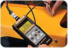
The instruments shown in Figures 1 and 2 are capable of calibration on a coating over a ferrous substrate. In this case, a new zero point and one additional point will be determined to adjust the calibration to the measuring object. To perform a calibration on a coating, the user should have a coated part with the same geometry and the same substrate material to be measured. In other words, if the user is measuring a cylindrical part, the calibration on the coating should be made over the same cylindrical part that needs to be measured.

Each probe may have a specific advantage in addition to the ability to measure a certain part. For instance, it might be well suited for measuring over a rough surface, measuring a soft coating, or measuring a coating that still has a wet (acidic) content (typical of anodized aluminum). Still other probes have different measurement ranges that could be as thick as 2 in. The measurement of duplex coatings used in the automotive industry - for instance, where the uniformity of zinc and the thickness of paint applied to zinc over steel must be known - is another example of a specific probe advantage. In this case, the user benefits by seeing the simultaneous thickness of both the zinc and the paint. Regardless of the application, users should consider the measurement range, accuracy, precision and other parameters when selecting a probe.
One challenge faced by facilities that use interchangeable coating thickness probes is constantly having to calibrate and verify gauge accuracy each time the probe and the type of part to be measured are exchanged. Technology advances have led to the development of “smart probes” that have built-in memory chips. When combined with the coating thickness gauge, these chips store variables such as geometry and material characteristics. This technology allows the user to verify gauge accuracy and store up to 100 different application settings to accommodate for the previously mentioned factors that influence coating thickness measurement.
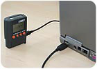
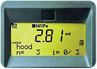 Figure 4 demonstrates data transfer using wireless and USB capabilities. Values can be taken and sent to a computer up to 60 ft. away in real time. A powder coating shop that measures parts as they are coming off the rack can have the reports completed and included with the shipment to the customer in a short amount of time using this method. An additional capability includes naming on the coating thickness instrument display the area(s) that are being measured (see Figure 5). Such labeling greatly reduces the chance that data meant for one area or part is mistakenly recorded for a different area or part.
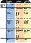 Figure 6 summarizes how all of the data can be processed and transferred. Again using the automotive market as an example, values representing each individual hood can be expanded to include the average values for all of the hoods per shift, week, month, etc. Real trends and cost savings can be achieved by monitoring film thickness in such a manner.
Fischer Technology, Inc.’s website is at www.fischer-technology.com.
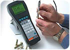
Figure 1. Some instruments, such as the Fischer Dualscope, are capable of calibration on a coating over a ferrous substrate.
Common coating thickness applications include measuring paint or powder coating over ferrous and nonferrous substrates. Other applications could be measuring plating thickness over steel or anodize over aluminum. Measurement methods used by handheld coating thickness gauges include magnetic induction for measuring nonmagnetic coatings applied to a ferrous metal, or an eddy current method for measuring nonconductive coatings over a nonferrous substrate, such as aluminum. The phase-sensitive eddy current method has significant advantages for measuring metallic coatings applied to parts with various shapes.
Regardless of the application, those who measure coating thickness should be aware of technology that has been developed to assist in meeting their measurement challenges. These technological advances include new calibration options, interchangeable probes, data documentation and solutions for nonstandard applications.
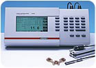
Figure 2. Another example of an instrument that is capable of calibration on a coating over a ferrous substrate.
Calibration on the Coating
Calibration and verification of accuracy is described in ASTM D 7091 Standard Practice for Nondestructive Measurement of Dry Film Thickness of Nonmagnetic Coatings Applied to Ferrous Metals and Nonmagnetic, Nonconductive Coatings Applied to Nonferrous Metals. Many manufacturers of coating thickness instruments strongly recommend verifying and adjusting the instruments using a non-coated substrate similar to what will be coated. This test is conducted using a certified Mylar foil with a known thickness. First, measurements are taken on the non-coated part to get a stable “zero” reference. The foil is then placed on top of the non-coated part. A series of readings are taken, and an adjustment is made to the value on the display to match the thickness of the foil. A non-coated part should be used as the “zero” reference because of factors that influence readings, including curvature, edge effect, substrate thickness, surface roughness, permeability and conductivity.Quality control and incoming inspection departments typically check the work of their suppliers. However, if the supplier is several states away, then a non-coated part might not always be available. This is especially true if the part is too large to ship or otherwise very expensive. Calibration on the coating is a unique method that allows the user to take into account the various factors that influence coating thickness without needing to have access to a non-coated part.
The instruments shown in Figures 1 and 2 are capable of calibration on a coating over a ferrous substrate. In this case, a new zero point and one additional point will be determined to adjust the calibration to the measuring object. To perform a calibration on a coating, the user should have a coated part with the same geometry and the same substrate material to be measured. In other words, if the user is measuring a cylindrical part, the calibration on the coating should be made over the same cylindrical part that needs to be measured.
Figure 3. For parts that cannot be measured with the same probe, an instrument capable of accepting interchangeable probes is a benefit.
Coating Thickness Measurement Probes
Coatings are applied to all kinds of parts with various geometrical shapes, including inner diameter areas. A manufacturer of automotive components, for instance, may have many parts that cannot be measured with the same probe. Therefore, having an instrument capable of accepting interchangeable probes is a benefit. Figure 3 shows some of the various coating thickness probes available.Each probe may have a specific advantage in addition to the ability to measure a certain part. For instance, it might be well suited for measuring over a rough surface, measuring a soft coating, or measuring a coating that still has a wet (acidic) content (typical of anodized aluminum). Still other probes have different measurement ranges that could be as thick as 2 in. The measurement of duplex coatings used in the automotive industry - for instance, where the uniformity of zinc and the thickness of paint applied to zinc over steel must be known - is another example of a specific probe advantage. In this case, the user benefits by seeing the simultaneous thickness of both the zinc and the paint. Regardless of the application, users should consider the measurement range, accuracy, precision and other parameters when selecting a probe.
One challenge faced by facilities that use interchangeable coating thickness probes is constantly having to calibrate and verify gauge accuracy each time the probe and the type of part to be measured are exchanged. Technology advances have led to the development of “smart probes” that have built-in memory chips. When combined with the coating thickness gauge, these chips store variables such as geometry and material characteristics. This technology allows the user to verify gauge accuracy and store up to 100 different application settings to accommodate for the previously mentioned factors that influence coating thickness measurement.
Figure 4. An example of data transfer using wireless and USB capabilities.
Data Transfer of Coating Thickness Measurements
Documentation of coating thickness measurements is an important quality assurance function. Trends in spray patterns and/or coverage can be monitored if the data are processed and tracked. Technological advances such as wireless or USB data transfer make such processing and tracking possible.Figure 5. Some instruments allow the area(s) that are being measured to be named on the display.
Figure 6. Data from different production lines can be processed and transferred using wireless or USB capabilities.
Figure 7. This instrument uses the phase-sensitive eddy current method and is capable of measuring the coatings applied to very small parts, such as fixtures, screws, nuts and bolts.
Phase-Sensitive Eddy Current Method
While standard paint and powder coating thickness measurement requirements can be accomplished using the magnetic induction or eddy current methods, some situations require a different technique. The phase-sensitive eddy current method is well suited for copper thickness measurement in PC board boreholes and surface copper thickness measurement on PC boards. It is also suited for measuring nonferrous metal coatings, such as copper, aluminum or brass over a nonferrous or electrically nonconductive substrate. The unit shown in Figure 7 uses the phase-sensitive eddy current method and is capable of measuring the coatings applied to very small parts, such as fixtures, screws, nuts and bolts.Improved Coating Thickness Measurement
Several recent technological advances in the field of coating thickness measurement have been focused on improving accuracy, providing solutions to new applications and simplifying data documentation. These include instruments capable of calibration on the coating, probes for specific tasks, wireless data communication, and phase-sensitive eddy current instruments capable of nonstandard coating thickness measurement. Users of coating thickness gauges and probes should always review the operating manual, as well as the measurement range, measurement precision and technical data published by the manufacturer, to select the most appropriate unit for the measurement requirement.Fischer Technology, Inc.’s website is at www.fischer-technology.com.
Looking for a reprint of this article?
From high-res PDFs to custom plaques, order your copy today!


