The Importance of Accurately Measuring Film Thickness
Coating thickness plays an important role in product quality, process control and cost control, and it can be measured with many different instruments. Understanding the equipment that is available for film thickness measurement and how to use it is useful to every coating operation.
The issues that determine what method is best for measuring a particular coating include the type of coating, the substrate material, the thickness range of the coating, the size and shape of the part, and the cost of the equipment. Techniques for measuring cured organic films include nondestructive and destructive dry-film methods. Methods are also available for powder and liquid coatings that measure the film before it is cured.
Magnetic film gauges are used to nondestructively measure the thickness of a nonmagnetic coating on ferrous substrates. Most coatings on steel and iron are measured this way. Magnetic gauges use one of two principles of operation: magnetic pull-off or magnetic/electromagnetic induction.
Magnetic pull-off gauges use a permanent magnet, a calibrated spring and a graduated scale. The attraction between the magnet and the magnetic steel pulls the two together. As the coating thickness separating the two increases, it becomes easier to pull the magnet away. Coating thickness is determined by measuring this pull-off force.
Thinner coatings will have stronger magnetic attraction while thicker films will have comparatively less magnetic attraction. Testing with magnetic gauges is sensitive to surface roughness, curvature, substrate thickness and the makeup of the metal alloy.
Magnetic pull-off gauges are rugged, simple, inexpensive, portable and usually do not require any calibration adjustment. They are a good, low-cost alternative when quality goals require only a few readings during production.
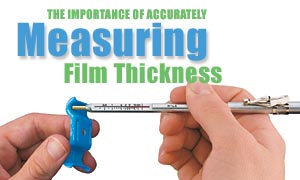
Pencil-type models use a magnet that is mounted to a helical spring that works perpendicularly to the coated surface. Most pencil-type pull-off gauges have large magnets and are designed to work in only one or two positions, which partially compensate for gravity.
A more accurate version has a tiny, precise magnet to measure on small, hot or hard-to-reach surfaces. A triple indicator ensures accurate measurements when the gauge is pointed down, up or horizontally and has a tolerance of plus or minus 10%.
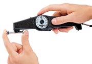
Rollback dial models are the most common form of magnetic pull-off gauge. A magnet is attached to one end of a pivoting balanced arm and connected to a calibrated hairspring. By rotating the dial with a finger, the spring increases the force on the magnet and pulls it from the surface.
These gauges are easy to use and have a balanced arm that allows them to work in any position, independent of gravity. They are safe in explosive environments and are commonly used by painting contractors and small powder coating operations. Typical tolerance is plus or minus 5%.
Magnetic and electromagnetic induction
Magnetic induction instruments use a permanent magnet as the source of the magnetic field. A Hall-effect (voltage that is generated transversely to the current flow direction in an electric conductor-the Hall voltage-if a magnetic field is applied perpendicularly to the conductor) generator or magneto-resistor is used to sense the magnetic flux density at a pole of the magnet. Electromagnetic induction instruments use an alternating magnetic field. A soft, ferromagnetic rod wound with a coil of fine wire is used to produce a magnetic field. A second coil of wire is used to detect changes in magnetic flux.These electronic instruments measure the change in magnetic flux density at the surface of a magnetic probe as it nears a steel surface. The magnitude of the flux density at the probe surface is directly related to the distance from the steel substrate. By measuring flux density, the coating thickness can be determined.
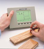
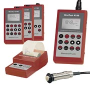
Electronic magnetic gauges come in many shapes and sizes, including hand-held gauges and bench-top models. They commonly use a constant pressure probe to provide consistent readings that are not influenced by different operators. Measurement stands are also available to reduce the variance of measurements from operator to operator. Readings are shown on a liquid crystal display (LCD). They can have options to store measurement results, perform instant analysis of readings, and output results to a printer or computer for further examination. Typical tolerance is plus or minus 1%.
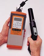
Electronic gauges are available with either a built-in probe or a probe on a cable. Integrated probes are ideal for larger parts while gauges with a probe attached to a cable allow for better positioning of the probe on parts with different geometric shapes. Some manufacturers offer a wide range of separate probes for hand-held and bench-top models that can be exchanged in the future if the application changes.
The manufacturer's instructions should be carefully followed for the most accurate results. Standard test methods are available in ASTM D 1186, ISO 2178 and ISO 2808.
Eddy current
Eddy current techniques are used to nondestructively measure the thickness of nonconductive coatings on nonferrous metal substrates. A coil of fine wire conducting a high-frequency alternating current (above 1 MHz) is used to set up an alternating magnetic field at the surface of the instrument's probe. When the probe is brought near a conductive surface, the alternating magnetic field will set up eddy currents on the surface.The substrate's characteristics and the distance of the probe from the substrate (the coating thickness) affect the magnitude of the eddy currents. The eddy currents create their own opposing electromagnetic field that can be sensed by the exciting coil or by a second, adjacent coil.
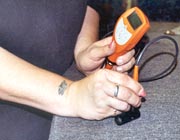
Eddy current coating thickness gauges are used to measure coating thickness over all nonferrous metals. Like the electronic gauges, they commonly use a constant pressure probe and display results on an LCD.
They can also have options to store measurement results or perform instant analysis of readings and output to a printer or computer for further examination. The typical tolerance is plus or minus 1%. Testing is sensitive to surface roughness, curvature, substrate thickness, type of metal substrate and distance from an edge.
However, in some cases, they can be compensated or reduced with specialty probes. For instance, a double pole probe can reduce the effects of substrate surface roughness. Curvature of the part or parts can also be compensated with an axial, single-tip measurement probe with a spring-loaded measuring system.
This type of probe would be ideal for an aluminum blind or an auto body component that is curved. In addition to getting a base metal reading on the uncoated substrate, a shim or standard, usually made of mylar, can be used to adjust the gauge to optimize and improve the accuracy.
Standard methods for the application and performance of this test are available in ASTM B 244, ASTM D 1400 and ISO 2360.
Some gauges incorporate both magnetic and eddy current principles into one unit. Some simplify the task of measuring thickness on different substrates by switching automatically from one principle of operation to the other, depending upon the substrate.
Ultrasonic technique
The ultrasonic pulse-echo technique is used to measure the thickness of coatings on nonmetal substrates without damaging the coating.The probe of the instrument contains an ultrasonic transducer that sends a pulse through the coating. The pulse reflects back from the substrate to the transducer and is converted into a high-frequency electrical signal. The echo waveform is digitized and analyzed to determine coating thickness. In some circumstances, individual layers in a multilayer system can be measured.
A typical tolerance for this device is plus or minus 3%. Standard methods for the application and performance of this test are available in ASTM D 6132.
Beta Backscatter Method
The Beta Backscatter Method uses a beam of beta particles from a beta-emitting isotope. The beam is directed through an aperture onto the coated component and a proportion of these particles is "backscattered" from the coating through the aperture to penetrate the very thin window of a Geiger Muller (GM) tube.The gas of the GM tube ionizes, causing a momentary discharge across the GM tube electrodes. The pulse of the discharge is counted by an electronic counter and translated into coating thickness.
The Beta Backscatter method is typically used to measure organic coatings over ferrous or nonferrous substrates when the geometry of the part is too small for a magnetic induction or eddy current technique. It is also ideal for very thin coatings that are unable to be measured accurately with a magnetic induction or eddy current gauge.
Micrometer
Micrometers are sometimes used to check coating thickness. They have the advantage of measuring any coating/substrate combination but the disadvantage of requiring access to the bare substrate. The requirement to touch both the surface of the coating and the underside of the substrate can be limiting and they are often not sensitive enough to measure thin coatings.
Two measurements must be taken: one with the coating in place and the other without. The difference between the two readings, the height variation, is the coating thickness. On rough surfaces, micrometers measure coating thickness above the highest peak.
Destructive tests
One destructive technique is to cut the coated part in a cross section and measure the film thickness by viewing the cut microscopically. Another cross sectioning technique uses a scaled microscope to view a geometric incision through the dry-film coating.A special cutting tool is used to make a small, precise V-groove through the coating and into the substrate. Gauges are available that come complete with cutting tips and an illuminated scaled magnifier.
While the principles of this destructive method are easy to understand, there are opportunities for measuring error. Preparing the sample and interpreting the results requires skill. Adjusting the measurement reticule to a jagged or indistinct interface may create inaccuracy, particularly among different operators.
Destructive testing is used when inexpensive, nondestructive methods are not possible, or as a way of confirming nondestructive results. ASTM D 4138 outlines a standard method for this measurement system.
Measurement before cure
Wet-film thickness gauges help determine how much liquid paint needs to be applied wet to achieve a specified dry-film thickness, provided that the percent of solids by volume is known. They measure all types of wet organic coatings, such as paint, varnish and lacquer on flat or curved, smooth surfaces.Measuring wet-film thickness during application provides the operator with immediate feedback so that errors from inaccurate film thickness can be avoided. Light film can sometimes be corrected by adding more coating, but this will cost money and may lead to other costly quality problems.
If the film is too heavy, it is a waste of money and may cause problems with fit or other performance issues. Correction of the film after it has dried or chemically cured requires costly extra labor and risk.
The equations for determining the correct wet-film thickness (WFT), both with and without thinner, are as follows:
Without thinner:
WFT = desired dry-film thickness
% of solids by volume
With thinner:
WFT = desired dry-film thickness / % of solids by volume
100% + % of thinner added
Wet film is most often measured with a wet-film comb or wheel. The wet-film comb is a flat aluminum, plastic or stainless-steel plate with calibrated notches on the edge of each face. The gauge is placed squarely and firmly onto the surface to be measured immediately after coating application and then removed.
The wet-film thickness lies between the highest coated notch and the next uncoated notch. Notched gauge measurements are neither accurate nor sensitive, but they are useful in determining approximate wet-film thickness of coatings on articles where size and shape prohibit the use of more precise methods (ASTM D 1212).
The gauge should be used on smooth surfaces, free from irregularities, and along the length, not the width, of curved surfaces. Using a wet-film gauge on quick-drying coatings will yield inaccurate measurements. ASTM D 4414 outlines a standard method for measuring wet-film thickness by notch gauges.
A wet-film wheel (eccentric roller) uses three disks. The gauge is rolled in the wet film until the center disk touches the wet film. The point where it makes contact provides the wet-film thickness.
Powder coatings can be measured prior to curing with a simple hand-held comb or an ultrasonic gauge. The uncured powder film comb works much the same way as a wet-film gauge. The comb is dragged through the powder film and the thickness lies between the highest numbered tooth that made a mark and has powder clinging to it.
These gauges are relatively inexpensive and have an accuracy of plus or minus 5µm. They are only suitable as a guide since the cured film may be different after flow. Marks left by the gauge may affect the characteristics of the cured film. Also, electrostatic behavior may impact the attraction of powder material to the teeth of the comb and confuse the results.
An ultrasonic device can be used nondestructively on uncured powder on smooth metallic surfaces to predict the thickness of the cured film. The probe is positioned a short distance from the surface to be measured and a reading is displayed on the LCD of the device. Measurement uncertainty is plus or minus 5µm.
Another device for measuring powder prior to cure uses a specially designed probe. Actual applied powder thickness is measured, and then, after baking, the cured thickness is measured with a conventional probe. The difference in thickness is the "shrinkage" factor of the powder as it goes through the baking process.
That factor can then be confidently applied to powder thickness measurements at the point of application to determine the actual dry-film thickness, saving time, materials and powder during the setup process and production. Post-bake measurements at that point would only be necessary for periodic verification purposes.
Thickness standards
Coating thickness gauges are calibrated to known thickness standards. There are many sources of thickness standards, but it is best to ensure they are traceable to a national measurement institute such as the National Institute of Standards & Technology. It is also important to verify that the standards are at least four times as accurate as the gauge they will be used to calibrate. A regular check against these standards verifies the gauge is operating properly. When readings do not meet the accuracy specification of the gauge, it must be adjusted or repaired and then calibrated again.Film thickness in coatings can significantly impact cost and quality. Measurement of film thickness should be a routine event for all coaters. The correct gauge to use depends on the thickness range of the coating, the shape and type of substrate, the cost of the gauge, and how critical it is to get an accurate measurement.
Looking for a reprint of this article?
From high-res PDFs to custom plaques, order your copy today!

