Let the Math Drive the Mover
Oscillators and reciprocators on the other hand provide coaters with greater control relative to lapping of fan patterns to achieve a more uniform average film build. "Lapping" or "perfect lap" is defined such that at the end of a complete cycle (one up and one down stroke), a gun spray pattern ends up right next to its initial position on the part without any overlap between the patterns, such as you will see in Figures 4 and 5 later. In other words, if configured properly as I will demonstrate, the conveyor travels the distance of E/2 (E = effective fan pattern width) during one stroke of an oscillator or reciprocator. With perfect lap, every inch of the part's surface is coated twice.
One of the more important points that hopefully you will take away from this article is that in most cases, both an oscillator and a reciprocator will coat the same part effectively and efficiently, if configured properly. However, much confusion has been created in the industry, and in the customer's mind, as suppliers of powder coating equipment often try to sell one machine against the other. Thus, never before has the old adage "a smart consumer is an informed consumer" been more appropriate. The best approach to making the right selection in the first place is
1. Understand the capabilities of both oscillators and reciprocators.
2. Arm yourself with the proper tools to configure each machine for application.
3. Recognize that in most cases both oscillators and reciprocators will perform sufficiently if configured correctly.
First, I want to educate you about how to configure both oscillators and reciprocators for a specific application and provide some basic tools and knowledge for the everyday user of gun movers.
Then I will provide some final points for consideration for both types of machine from an application as well as a system perspective.
Oscillators: Short Stroke with Vertical Gun Arrangement
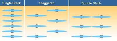
The objective here is to provide some basic tools for establishing the number of guns, determining gun center distance, and ascertaining stroke speed for an oscillator. Just like a reciprocator, if configured properly, an oscillator can apply an even, uniformly distributed coating - without heavy areas (or striping) and without light areas (voids). Three common types of oscillator gun setups include single stack, staggered and double stack (Figure 1). Note that each gun arrangement contains six guns. This is based on a specific part height of 60" (1.5 m), as you will see later when determining gun-to-gun center distance, stroke length and stroke speed.Single Stack. A single stack is preferred if "contouring" of a part is required, using an In/Out positioner to drive the oscillator in and out either between parts to coat the leading and trailing edges, or to coat inside a part - a large cabinet, for instance.
A single stack requires fewer gun slots, less open booth area, and potentially higher containment velocities. It also is likely the easiest gun configuration for an operator to set up in terms of gun spacing.
Staggered. Note that the staggered gun arrangement utilizes the same number of guns (six) as a single stack. Because of the resulting offset in gun spacing, a staggered gun arrangement reduces the potential for gun pattern impingement.
Double Stack. Again, as with the single stack and the staggered gun arrangement, the double stack utilizes six guns. However, due to the longer stroke length and greater gun-to-gun vertical center distance with six guns, this set-up might work better with two additional guns. At the same time, a double stack arrangement allows for lower flow rates, providing higher transfer efficiency (TE) with less powder spraying past the part to be coated.
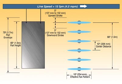

In any event, our overall oscillator/gun parameter calculation consists of six steps that include determining cycles per minute (CM), strokes per minute (SPM), gun centers (GC), gun stroke length (GSL), total stroke length (TSL), and oscillator stroke speed (OSS). Please note that the results of my calculation will be the same for a staggered gun configuration. For the double stack configuration, had six guns been used, the gun centers would be closer to 24" (609 mm) and the stroke length closer to 23" (584 mm). Had eight guns been used, the gun centers would be closer to 17" (431 mm) and the stroke length closer to 16" (406 mm).
Determining Cycles Per Minute (CM)
CM = Cycles per minuteLS = Line speed in feet per minute
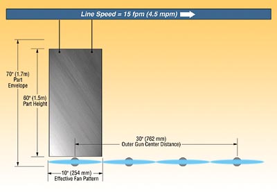
E = Effective fan pattern width in inches
CM = LS x 12÷E
CM = 15 fpm x 12÷10"
CM = 180÷10"
CM = 18
Note that one cycle is equal to one up stroke and one down stroke combined. Therefore, cycles per minute are always half the number of calculated strokes per minute.
Determining Strokes Per Minute (SPM)
SPM = Strokes per minuteCM = Cycles per minute
SPM = CM x 2
SPM = 18 x 2
SPM = 36
Determining Gun Centers
GC = Center distance between gunsPH = Part height
NGS = Number of spaces between guns
GC = PH/NGS
GC = 60"/5
GC = 12" (304 mm)
An experienced operator might determine number of guns by simply figuring one gun, centered with the top of the part, and an even gun spacing of 12" (304 mm). This would result in six guns per side for a 60" (1.5 m) tall part. Again, this is only a baseline configuration. The same part being coated at 15 fpm (4.5 mpm) may require fewer guns, or may require more. In fact while writing this article, the operating parameters for our coating scenario (60" tall part at 15 fpm) were plugged into two separately authored calculators. One calculator determined four and-a-half guns per side and another calculated seven guns per side. Again, the tools covered in this article and those available in Excel-based spreadsheets will often get you close, if not right on the money. At the same time, calculated results should be treated as baseline parameters that can vary depending on transfer efficiency, nominal effective fan pattern, etc. Ultimately, testing should be the deciding factor as to the best configuration for a particular part to be coated.
Determining Gun Stroke Length (GSL)
GSL = Gun stroke lengthGC = Center distance between guns
GSL = GC - 1" to 2"
GSL = 12" - 2"
GSL = 10" (254 mm)
Determining Total Stroke Length (TSL)
TSL = Total stroke lengthGC = Center distance between guns
NGS = Number of spaces between guns
SL = Stroke length
TSL = (GC x NGS) + SL
TSL = (12" x 5) + 10"
TSL = 60" + 10"
TSL = 70" (1.7 m)
Note that adjustments can be made to reduce overall stroke length. Depending on the depth of the part to be coated (required wrap) and other application variables, this can reduce the amount of over-spray at the top and bottom of the part. However, consideration should be given to adequate over stroke above the part and under stroke below the part so as not to create heavy edge buildup for example, or to achieve the desired amount of wrap as another example. In fact, many calculators assume only a 2" to 3" over stroke at the top and bottom of the stroke, providing enough distance for the effective fan pattern height to clear the top and bottom edges of the part. Again, our calculated results are only baseline parameters and may need to be adjusted slightly to meet coating and operating (powder material usage) requirements.
Determining Oscillator Stroke Speed (OSS)
OSS = Oscillator stroke speedCM = Strokes per minute
GSL = Gun stroke length
OSS = (CM x GSL) + 12÷6
OSS = (18 x 10) + 12÷6
OSS = 192÷6
OSS = 32 fpm (9.7 mpm)
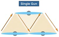
Determining oscillator stroke speed is the final step in configuring an oscillator. If configured properly the coverage should match that shown in Figure 4. Note that this graphic representation is of one gun only, simulating a part moving at line speed in front of a single gun that is oscillating up and down at a calculated stroke speed. The resulting coverage is known as "perfect lap" wherein even coverage of the part is obtained. As with reciprocators, double lapping can also be obtained. Although we will not cover how to calculate double lap here, the theory behind double lapping is to reduce gun flow rates and apply 1 mil (25 micron) for example with 2 passes for a total of 2 mils (50 micron), as opposed to 2 mils (50 micron) total coverage with only one pass. This theory supports the idea that more uniform coverage can be obtained by slowly building coverage with multiple passes as opposed to quickly building coverage with only one pass.
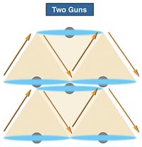
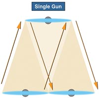
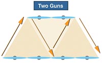
As with an oscillator, gun patterns shown in figures 7 and 8 represent perfect lap. The following calculations show how to calculate strokes per minute and reciprocator speed for one and two gun perfect lap scenarios. As with an oscillator, one stroke is one direction only, either up or down, while a cycle equals one down stroke and one up stroke combined.
Determining Strokes Per Minute (SPM) - One Gun Perfect Lap
SPM = Strokes per minuteC = Line speed in feet per minute
E = Effective fan pattern width
SPM = 24 x C÷E
SPM = 24 x 15÷10
SPM = 360÷10
SPM = 36
Determining Reciprocator Stroke Speed - One Gun Perfect Lap
RSS = Reciprocator stroke speedSPM = Strokes per minute
SL = Reciprocator stroke length in feet
RSS = SPM x (SL + 1.4167)
RSS = 36 x (5.8 + 1.4167)
RSS = 36 x 7.2167
RSS = 260 fpm (79 mpm)
Determining Strokes Per Minute (SPM) - Two Gun Perfect Lap
SPM = Strokes per minuteC = Line speed in feet per minute
E = Effective fan pattern width
SPM = 24 x C÷E
SPM = 24 x 15÷10
SPM = 360÷10
SPM = 36
SPM = 36÷2
SPM = 18
Determining Reciprocator Stroke Speed -Two Gun Perfect Lap
RSS = Reciprocator stroke speedSPM = Strokes per minute
SL = Reciprocator stroke length in feet
RSS = SPM x (SL + 1.4167)
RSS = 18 x (5.8 + 1.4167)
RSS = 18 x 7.2167
RSS = 130 fpm (40 mpm)
If you've been following along, you might notice that the stroke speeds resulting from my calculation far exceed the 100 fpm (30 mpm) stroke speed barrier. Therefore, a 60" (1.5 m) tall part at 15 fpm (4.5 mpm) would likely require four guns stacked horizontally to coat the part at a reasonable stroke speed. To determine this, take the single gun strokes per minute of 36, and divide by the number of guns, in this case 4. The resulting stroke per minute is now 9. Then calculate the reciprocator stroke speed as follows.
Determining Reciprocator Stroke Speed - Four Gun Perfect Lap
RSS = SPM x (SL + 1.4167)RSS = 9 x (5.8 + 1.4167)
RSS = 9 x 7.2167
RSS = 65 fpm (20 mpm)
65 fpm (20 mpm) for a part height of 60" (1.5 m) represents a more typical stroke speed.
Points To Consider
Number of Guns. The number of guns for both oscillators and reciprocators should be dictated by line speed, coating thickness, and transfer efficiency - not on the gun moving method. As shown, an oscillator may require anywhere from four to seven guns to coat a 60" (1.5 m) tall part at 15 fpm (4.5 mpm), depending on how it is calculated and what assumptions are made, but more importantly, how it performs in a test lab. It has been claimed that a reciprocator requires less guns than an oscillator at the same line speed and part height. While there may be some validity to this statement, the calculation indicates that a reciprocator stroke speed of approximately 69 fpm (20 mpm) with four guns may be slightly on the high side, requiring more guns to coat the part at a slower stroke speed.Coating Material Usage. To minimize heavy edge buildup on the top and bottom of a part, it is typical for both an oscillator and a reciprocator to include some amount of over-stroke. One thing to consider is with an oscillator and its vertical gun arrangement; only one or two guns are over-stroking at the bottom and the top of the part. With a reciprocator and its horizontal gun arrangement, all guns would be over-stroking at the top and the bottom of the part, resulting in a greater amount of over-spray and higher powder material usage.
Line speed. Typically for oscillators and reciprocators, the higher the line speed and/or the taller the part, the more guns are required to coat the part. This is one area in which reciprocators are somewhat limited. In some cases, where stroke speed exceeds the capability of the gun to coat effectively, more guns may be required, thus lengthening the width of the overall gun arrangement.
Booth Length. This is where oscillators have somewhat of an advantage, especially in situations with higher line speeds and/or tall parts. In most manufacturing plants, floor space is typically at a premium. If a reciprocator with a horizontal gun arrangement requires more than two guns, then the resulting increase in total gun spacing will cause the booth to grow longer.
Contouring. This is another area where oscillators have a slight advantage. Typical high production demands require minimal space between parts for greater line density. With the horizontal gun arrangement of a reciprocator, it is virtually impossible to move in between parts and coat (contour) the leading and trailing edges. An oscillator with its vertical gun arrangement is more effective for these types of applications.
Triggering and Zoning. Because of their differences in gun arrangements, different approaches are used to accommodate triggering and zoning. Because of the vertical gun arrangement of an oscillator, vertical zoning for short parts vs. tall parts for example is simply a matter of automatic no-part, no-spray control of the gun. Furthermore, for larger line gaps automatic no-part, no-spray would turn all of the guns off. Reciprocators on the other hand compensate for vertical zoning by triggering guns off at the bottom of the part, assuming no change in stroke and a common top datum. In combination, they may also change stroke length as well as stroke speed. Unfortunately, with all guns arranged horizontally, and with minimal part spacing to achieve maximum line density, this is extremely difficult to achieve in production.
Gun Failure. The argument has been made that reciprocators are more forgiving due to their horizontal gun arrangement, in the sense that if a gun were to fail fully or partially, the other guns would automatically "fill in the void" (compensate for any variability). This is not a valid argument. If this were true, then not all of the guns used should be required in the first place. Therefore, if a gun were to fail either partially or fully with either an oscillator or a reciprocator, a film thickness gage would detect non-uniform coverage in both cases.
If configured properly, both oscillators and reciprocators can coat the same part effectively. Based on that, there is one final recommendation that I want to share. Optimum application efficiency and optimum system efficiency are the best methods for determining the equipment configuration of a powder coating system, not the method of moving the guns.
Looking for a reprint of this article?
From high-res PDFs to custom plaques, order your copy today!


