Vacuum Milling Enables Purer, Faster Dispersion
Prefer the magazine experience? Subscribe to our digital edition here.
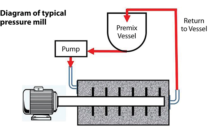
Decades have passed without any significant improvement in traditional vertical and horizontal in-line media milling designs. Feedstocks are predominantly pressure driven through an enclosed horizontal or vertical chamber filled with media and separated by a screening device. The separation area is relatively small, thereby contributing to what would be considered a painfully slow throughput rate when compared to a vacuum mill. The single media mill innovation that has made a significant performance advance is the immersion or basket mill; basically a large, stationary screening device containing media that passes feedstock through its rotating internal stirring apparatus at about 10 times the velocity of traditional in-line mills (Figure 1). It is submerged into the batch and creates its own throughput by way of self-generated suction and centrifugal force, as opposed to the in-line mill that stands alone alongside the batch and force fed by a pump.
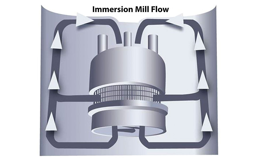
Some would argue that the slow throughput rate enables these older style mills to produce some products with just one pass, à la continuous process. On the other hand, multiple passes have test proven to be more productive in most instances, contributing to a smaller, narrower particle size. Consider now exactly what this means and what enables these different performances.
One-pass processing leads some to believe that it is analogous with continuous processing. Not true, if the premix is not continuous. Most premixes are made in dispersion tanks that produce batches which, once all the solids have been added, obtain a dispersion of some degree sufficient to be fed into a mill within an hour run time. The better the premix, the less time required to mill. Continuous pre-mixes are often put into a recirculation loop to improve what would often be considered unacceptable particle entry size for the media mill. Some coatings manufacturers ignore or downplay the importance of the pre-mix by either reducing the throughput rate of the mills or compensating for the poor pre-mix by using larger media and larger slot screens. This, of course, may result in passing through yet another media mill (in line) using smaller media and smaller screens to clean up what the larger media could not do.
What is the Price of This Process?
Let’s now look more closely as to how many users have followed the directives of kilowatt hours. Measuring expectations using this method is deceptive because it only tells us the amount of energy required to complete a milling to standard. It does not tell us how much of the energy has been wasted to operate in this manner.
Rolling shear and impact are two phenomenon that contribute to particle reduction. The by-product is heat. Another problem single-pass continuous milling can cause is that the amount of media employed is quite voluminous (and expensive), causing the feedstock to dwell in the chamber for extended periods of time. Although the heat can be somewhat controlled through cooling devices (water jackets and/or external heat exchangers) there is a cost in doing so, not only for the equipment required but also for the wasted energy.
Of course, to the best of prevalent knowledge, no process involving dispersion is heat-generation-free. The object is to shift the paradigm from high heat output transfer to higher energy transfer input to separate and break the feedstock particles. This results in lesser periods of time to reach standard, or a significant improvement in dispersion in the same time.
How Can This Be Done?
The answer is multiple passes. Very few dispersion processes are capable of being truly continuous. Of those few, there is likely a sacrifice in extracting the best possible qualitative results from the feedstock. A continuous recirculation through a closed loop from feed tank to mill can improve the process. Multiple passes reduce particle distribution bands and continue to reduce them up to the limitations of the media size and density. How is this possible without a proportional increase in dwell time? The answer is throughput.
Several years ago there was a discussion with some well-informed competitors who generally agreed with the concept of “improved performance in recirculation milling compared to continuous process.” Their experience of rapid recirculation was pumping about 50 gallons of feedstock (viscosity, rheology, etcetera, permitting) through a small in-line mill (2 liter) in one hour. When asked what our new in-line vacuum mill could deliver, the response was as follows: Under identical conditions of feedstock, media size, etc., our 2.5 liter mill……..50 gallons per minute. They did not believe this was possible.
How is This Possible?
The answer, in part, is a much larger screen with the same slot size. Larger screens enable more feedstock to flow in less time.
Even in EBD (electron beam drilled) screens with 0.1‑mm holes, the total open area is greater as the screen is increased in diameter and/or depth. The limitation then becomes the amount of media between the feedstock entry area and the screen. As the media field volumetrically increases, so does its blockage of feedstock throughput. The proper configuration is essential. Generally speaking, a vacuum mill can deliver better quality product in about the same time as a pressure mill (Figure 2) that uses twice the amount of media. Or, if you prefer, a vacuum mill can still produce a better-quality product in one quarter the time of a comparably media-loaded pressure mill.
Why does it matter if the feedstock is pumped or vacuumed into the mill? A pump merely pushes the pre-mix and whatever air is contained in it through the media field. Yes, there are impellor designs that help propel or repel the flow, but the air remains in the mix and inhibits particle dispersion as it acts as a cushion between the media and the particles. Additionally, internal pressure in the mill must be repelled by expensive, difficult-to-replace mechanical seals.
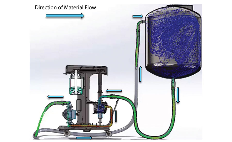
By placing a media-friendly pneumatic pump at the output side of the mill, suction creates a vacuum within the mill and begins to separate the air from the feedstock. The head pressure from the slurry holding/recirculation tank propels the slurry through a feed line to the mill (Figure 3). At this point the flow in the feed line is laminar with very little turbulence, as calculated by the dimensionless Reynolds number. For example, a slurry with a viscosity of 2,000 cps will generate a Reynolds number of about 29 as it flows through a 3” line. Turbulence begins with a Reynolds number of about 7,500 and is created and amplified as the slurry enters the media grind chamber. Turbulent flow incorporates air as you can observe during the premixing stage of slurry production. As the air-laden slurry enters the grind chamber, the suction created by the pump on the downstream discharge generates a vacuum within the grind chamber.
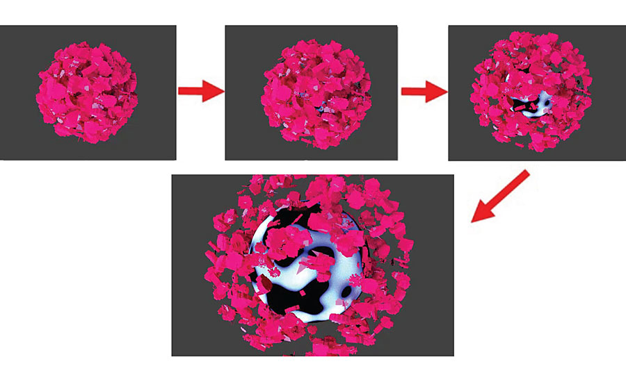
Small amounts of air entrapped as bubbles within the agglomerates begin to expand and push apart the solids in which they are entrapped (Figure 4). As this occurs, the air separates from the solids and begins to accumulate. The mill purges the air intermittently in large pockets as it forms in the pocket above the grind chamber. As the air pocket increases in size and pressure, it overcomes the competing force of the exiting feedstock and discharges itself as a now separate component of the premix. This cycle continues to repeat itself as the feedstock moves towards becoming a finished product.
Water-based products tend to hold air more readily than solvent-based ones. However, since the air is already a gas, it is removable usually with little concern for basic formulation ingredient loss. This is due, in part, to the differential in vapor pressures between water and solvent, both of which are liquids and dependent upon temperature at atmospheric pressure. As a vacuum develops in the mill chamber, air is extracted from the feedstock before the water can vaporize.
In the case of solvent-based products, as the temperature rises, the low vapor pressure of the solvent results in evaporation, and the solvent vapor is vacuumed along with the feedstock into the recirculation tank where it drops in temperature while mixing with the large quantity of cooler feedstock and reverts back to a liquid. The air being returned to the recirculation tank remains a gas and escapes the feedstock in the recirculation tank where it either stabilizes above the feedstock or is further evacuated from the tank through a vacuum differential between the grind chamber (higher vacuum) and the recirculation tank itself (lower vacuum).
Since heat influences evaporation, is it possible that the vacuum mill does not have a more severe heat extraction problem than a pressure mill? Heat is a form of energy in movement within particles. All particles have kinetic energy, with solids having the smallest amount of movement and gases having the largest amount. Dispersion (shear and impact) increases particle movement, thereby raising the average kinetic energy of the particles and increasing their overall temperature. Mills use a combination of conduction and convection for heat exchange. Vacuum mills also rely on both, but since air (gas) has the largest amount of movement (internal energy), its extraction is exceptionally beneficial to the conduction and to the remaining solids and liquids.
What is the Benefit of Air Reduction or Total Elimination?
The answers are:
- Less mill time;
- Product purity;
- Improved potency;
- More accurate volumetric and gravimetric measure;
- Elimination of an important variable (air);
- Improved performance using micro media (down to .03 mm);
- 50% reduction in media or up to 200% time reduction using comparable media loading of a pressure mill;
- Significant increase in energy efficiency.
By removing the air, the purity and potency of the product become more pronounced, as does the reduction in processing time. This is easily confirmed by observing the recirculation holding tank level at the beginning of the process and comparing it to the end. In most dispersions it can account for as much as 10% to 20% of the batch volume. Such change makes end results more predictable and less likely to cause filling difficulties.
As indicated in the fourth bullet above, air within the product affects its specific gravity and can be problematic when filling into cans. If the entrained air escapes from the product into the space within the container, the container would then not look full and could give another negative perception of the product.
Inks containing air, for example, will not look as smooth and glossy in the can, which contributes to a negative perception of the quality when the can is opened.
How Can a Vacuum Mill Be Less Expensive to Operate Than a Pressure Mill?
Vacuum mills use lower-cost commercial seals that last longer than pressure seals. They can do this because the feedstock and media within the mill are constantly vacuumed away from the seal, thus minimizing contamination wear as well as external leakage common to pressure mills. Additionally, since energy is more efficiently infused, fewer KWH are needed to reach standard as compared to a pressure mill. That is because feedstock is now replacing the air that would otherwise absorb energy going to waste. Approximately 50% less media is needed to match or exceed the degree of dispersion required to reach standard compared to a pressure mill. Stated another way, using comparable media loadings to a pressure mill, the vacuum mill can deliver superior results in 200% less time.
A low-cost commercial vacuum seal incorporated into the mill may outlast proprietary pressure seals since the internally generated vacuum is generally lower than the potential pressure in traditional mills. The seal takes about one hour to replace and is more forgiving when being installed.
For more information, visit www.hockmeyer.com.
Looking for a reprint of this article?
From high-res PDFs to custom plaques, order your copy today!


