New Technology for Powder Coating Bicycle Frames
Powder coating is a dynamically developing field used in the wider spectrum of industrial production. The advantage of this kind of surface treatment is the speed, quality and durability of the paints and their various uses. The mechanical, physical and chemical properties of the colors themselves are very favorable as well. Shortcomings of powder coatings arise from the necessary thickness of the coating layer and the physical process of coating a product. These shortcomings mainly occur during application and curing. Some of the problems arise due to the traditional hook and chain conveyor used in applying powder coatings.1The authors of this paper have considered one of the possibilities of the logistics in this field in order to eliminate these disadvantages.1-3
Existing Powder Coating Methods
Powder coating is applied as a free-flowing dry powder. The main difference between conventional liquid paint and powder paint is that powder coating does not require any kind of thinners. Newer technologies allow powder coatings to be applied to non-conductive materials, such as fiberboard and ceramics.2,3 The authors of this paper work with the basic principle of applying powder coating on electrically conductive surfaces.1,4
The electrostatic method includes a pre-treatment for the application of electrostatically charged particles (where the charging takes place in the mouth of the gun) of the powder coating to the part that has the opposite charge (which is grounded).2,3 This paint will stick to the surface until it is heated in a curing oven at a temperature of approximately 180 °C where it is melted. This thick liquid creates a nearly perfect continuous coating as it adheres well to a surface.5-10
Advantages of Powder Coating
A surface protected by a layer of powder paint is more resistant to scratches and the impact of different objects. Powder coating is also resistant to various chemicals.. It also exhibits lower process costs and allows for the recycling of colors. Powder coating can also be regarded as more environmentally friendly than wet paint.7,8,11
Disadvantages of Powder Coating
Powder coating technology entails a number of disadvantages both during the application process in addition to the final quality. These disadvantages arise from the physical and mechanical properties of the material.8 Powder coating acts as a thick liquid after heating; the molecules in it are naturally trying to achieve the smallest possible surface tension. This is a completely natural process. The coated material will wrap with the substrate, but it also fills in places where the coat may not be wanted (dents, threads, mounting holes, etc.). The thickness can be from 10 to 50 μm or more.8,10,11
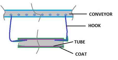
The powder coating process is usually done on chain conveyors, where the individual components hang on hooks or a supporting frame in serial or mass production (Figure 1).6,12-14 The hook design can also sometimes pose problems.
Experimental Methods and Materials
Powder Coating Tube Frames
Powder coating of tube frames has a lot of possibilities. It is usually possible to mask holes by means of cork or silicone seals. Another method is to remove the powder from the holes with compressed air. The existing chemicals that are present in there help to give good results as well.14-17
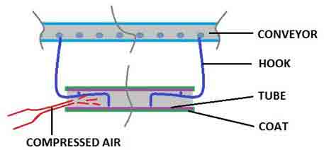
Figure 1 shows an illustration of a tube profile and the disadvantages of powder coating, which can penetrate into the inner parts and may stick to the points of contact with the painted hook component.
|
|
FIGURE 1 |Tube profile and the disadvantages of powder coating. |
Powder Coating Bicycle Frames
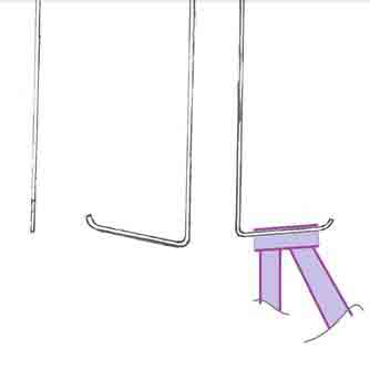
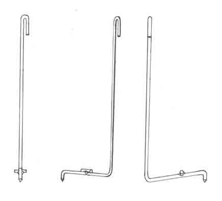
Bicycle frames have a number of holes for the installation of brackets, the axis etc. Unfortunately, the powder coating can seep into these holes, but should not remain there because of its thickness. The authors of this paper have done some research regarding the assembly possibilities and have described the worst problems. The badly designed hook was one of these problems (Figure 2).
|
|
FIGURE 2 | Badly designed hook. |
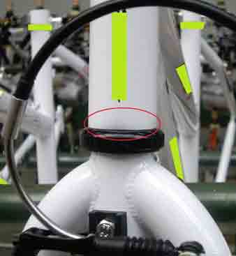
The main problem was that the powder coating could not cover the entire area (Figure 3) and, and the transfer of the electric charge was bad as well.11,18
|
|
FIGURE 3 |Paint defect where a bad hook was used. |
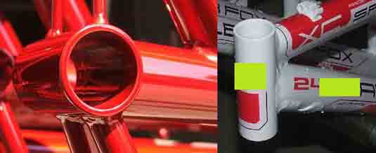
The thick layer of paint on the thread for the bottom bracket parts and a hole for the headset were anotherproblem (Figure 4). The coating layer in these areas is about 30-40 μm; it is not possible to mount other parts.
|
|
FIGURE 4 |The layer of paint in the construction holes and threads. |
Sample Calculation of Coating Consumption
The general formula for calculating powder coating consumption for bicycle frames is shown in the following formula.12,15
Cc = (2πdSSlSS + 2πdCSlCS + πdSTlST + πdTTlTT +πdDTlDT + πdHTlHT + 2πdFTlFT + Sx)t (1)
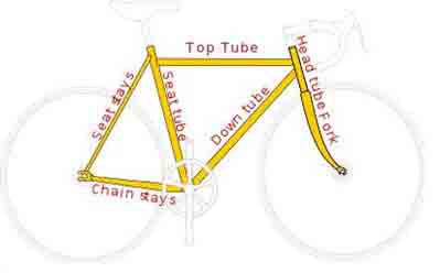
where: Cc is powder coating consumption;d is the diameter of the tube [mm];l is the length of the tube [mm];Sx is another area of specific tubes or parts [mm2];t is the thickness of the powder coating; subscripts:SS are seat stays (2 tubes); CS ischain stays (2 tubes);ST is the seat tube; TT is the top tube; DT is the down tube; HT is the head tube; and FT is the fork tube.
For clarity, the above mentioned subscripts from the formula are shown in Figure 5.
|
|
FIGURE 5 |Parts of a bicycle frame. |
A sample calculation of the powder coating consumption for this particular bicycle frame (specific frame where two top tubes are joined with seat stays)is shown in the following Formulas (2), (3).
S = (2πdSSlSS + 2πdCSlCS + πdSTlST + πdDTlDT + πdHTlHT + 2πdFTlFT + Sx) (2)
The top tubes are the same type as seat stays and will be calculated together, Sx = 17 000 mm2 (area of tube for BB parts and support for kickstand). For “t”, 0.03 mm thickness was chosen.
V = (2*π*17*1 050 + 2*π*17*380 + π*350*460 +
π*350*420 + π*35*140 + 17 000)*0.03 (3)
V = 34582.456 mm3 = 34.6 cm3
The powder coating consumption for the specific bicycle frame where two top tubes are joined with seat stays is approximately 34.6 cm3.
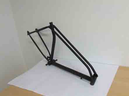
A bicycle frame where two top tubes are joined with seat stays that was painted by powder coating technologyis illustrated in Figure 6.
|
|
FIGURE 6 | Bicycle frame painted by the powder coating method. |
The Powder Coating Process
After having completed the measuring and analysis, the concept of a better powder coating technology was developed.
First of all, a better end of the hook for hanging was designed and tested. This design allows for locking tubes, the transfer of electric charge and the blowing of the unwanted powder from the bowels by means of compressed air.4,10,14,17-19
This solution allows for the installation of other components needed to have the extrusions with the prescribed clearances, without the need to take into consideration the thickness of the paint.3,4,7
The description and testing of the powder coating process was then done. The main aspects are described in Table 1. 13,14,20 This technology does not describe the preliminary process and the activities after unhanging the frames from the conveyor.
TABLE 1 | Description and testing of the powder coating process.
| Number of workers | 5 (master, master´s assistant, 2 co-workers in coating cabin, mechanic) |
| Special aids, needs | Compressed air (approx. 4 bar), the vacuum cleaner with tubes, the plugs for big holes (of the bottom bracket), the plastic foil to mask big holes |
| Master´s work | Hanging the frames on the conveyors, unhanging and controlling the painted frames, taking off the plugs |
| Master´s assistants work | The application of the plugs for the frames before coating, helping with the hanging and unhanging, the vacuuming the excess powder from the specific montaging parts of the frames |
| Co-workers work | Blowing the compressed air from the threads and mounting parts, the controlling and repairing the layer of the coating in the coating cabin |
| Mechanic´s work | The maintenance of the conveyor and purity, the refilling of powder to powder tray |
| Production of this group | It depends on the possibilities of the curing oven, about 80 bicycle frames per hour |
The coating phase
The coating phase can be divided into the following steps:3,6,11,13
· Conducting the application box automatically or manually. It is necessary to check the layer of powder coating and function of the forks during the deposition.
· Applying the powder to the point sensitively by TRIBO-handgun where it is not fixed by means of the automatic application.
· Purging the inner part of the head tube (using the compressed air).
· Removing the powder from the thread for the rear derailleur fixation and the transparent plastic foil from the seat tube.
· Vacuuming the layer of paint from the crease at the end of the derailleur (if the frame belongs to it).
· Checking visually and possibly removing the impurities from the fallen powder in the cabin, for example by vacuuming.
· Reporting each problem immediately to the master.
B: The phase before curing
· The master performs a visual inspection of the conveyor frames that lead to the curing oven. The workers will remove any deficiencies. The assistant that removes the plugs in the frames and extracts the layer of powder from the crease to end derailleur before the curing ovens may be present (if the frame belongs).
C: The phase after curing
The workers in the paint shop have to check the quality of the surface finish (visually, measuring the layer thickness, shade, etc.) if they unhang the frames from the conveyor. Any deficiencies in the quality of the finish are to be removed immediately or forwarded for repair.
The coated components must be hung on the conveyor hooks in order to enable the achievement of the integrity of the surface. In the ideal case, the hook is placed in places of the tube where the paint is not allowed.10,11 The undesirable powder may be removed from the bowels of the profile by blowing it out with compressed air. In the case of using the silicone seal, it may be removed manually, but again, with the risk of surface damage at the contact point.8,9,12
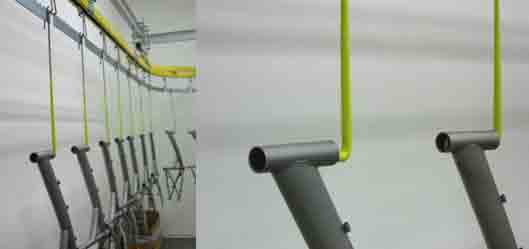
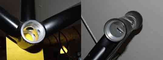
The new hook design and use of the hook in the longer tube are shown in Figures 7 and 8.
|
|
FIGURE 7 | The hook design for hanging bicycle frames. |
|
|
|
FIGURE 8 | The principle for hanging and cleaning the longer tube when using the designed hook. |
Results and Discussion
The authors of this paper applied this technology to the painting of bicycle frames; however it is possible to use the same technology in other cases. Positive results have been achieved and this allows for the fitting of the other components without the need for the complicated removal of the paint from unwanted places.1,13,14
The design of the hook for hanging allows the bicycle frame to hang so that the tip through the center of gravity of the frame is gently plunged into the material of the frame, which thereby allows for the transfer of the electrical charge.13,14There is no contact with the tube at its edge circumference, which allows for the creation of a coherent surface coating. On the basis of the realized observations when using the common chain conveyor, five workers can paint about 80 bicycle frames per hour.1,8,13,20,21
The series of frames on the conveyor are shown in Figure 9.
|
|
FIGURE 9 | The series of frames on the conveyor. |
The clean thread for the bottom bracket parts and the hole for the headset on the bicycle frame are illustrated in Figure 10.
|
|
FIGURE 10 | clean threads. |
Conclusion
The technology presented is complementary to existing powder coating technology. It has been expanded and its possibilities have been improved. Its application in practice may contribute to the improvement of the powder coating process of the tube profiles. 9,13
Only the hanging system and coating have been presented in this paper; the other parts of this technology are the subject of intellectual property of these authors.
References
1 Stanssens, DA, Van De Werff, AJ, Molhoek, L, Van Den Berg Jeths, R,“Developments on New Complete Binder for Powder Coatings.”, Waterborne, higher-solids, and powder coatings, 21st Symposium, LA, New Orleans, Feb. 1994
2 Van Der Linde, R, “Resin Composition and Process for the Preparation of this Resin Composition.” Patent No. 4,694,033, EP-PS 228 116, 1986
3 Smeets, PJ, Paas, CGM, Kraanen, WPM, “Resin Composition and Process for Preparing this Resin Composition.” EP-PS 377 258, 1990
4 Zhu, XY, Hu, L, Dong, M, “Synthesis andCharacterization of Silver-Coated CopperPowder Layer.” Key Engineering Materials512-515 (1) 141-146, (2012),doi:10.4028/www.scientific.net/KEM.512-515.141
5 Wong, W, Irissou, E, Legoux, JG, Vo, P, Yue, S, “Powder Processing and Coating Heat Treatment on Cold Sprayed Ti-6Al-4V Alloy.” Materials Science Forum 706-709 (1) 258 263, 2012,doi:10.4028/www.scientific.net/MSF.706-709.258
6 Blazek, J, Modern Treatments by Powder Paints. Bachelor thesis, Brno (2008)
7 Talbert, R, “Fundamentals of Powder Coating - Equipment and Process Advances Drive Applications.” Columnist from Products Finishing Magazine, Available at:http://www.pfonline.com/articles/fundamentals-of-powder-coating.
8 Hofer, R, Bigorra, J, “Biomass-based Green Chemistry: Sustainable Solutions for Modern Economies.” Green Chemistry Letters and Reviews 1 (2) 79-97 (2008)
9 Hale, J, Strengthening a Powder Coating Line, Products Finishing Magazine. Gardner Business Media, Cincinnati-Ohio (2013)
10 Merfeld, G, et al, “Development of Low Temperature Curing, 120°C, Durable, Corrosion Protection Powder Coatings for Temperature Sensitive Substrates.” Journal of Coatings Technology andResearch 2 (8) 661-668 (2005),doi: 10.1007/BF02774595
11 Misev, TA,Powder Coatings: Chemistry and Technology. R&D Uranox Seminar, Amsterdam (1996)
12 Scholz, K, “Powder Turnkey Systems.” Coatings Magazine(2004), Available at:http://www.gemapowdercoating.us/Portals/0/documents/pdflibrary/PartingtheCurtainArticle.pdf.
13 Kampf, R, Lizbetin, J, Lizbetinova, L, “Requirements of a Transport System User.” Communications 14 (4) 106-108 (2012)
14 Stopka, O, Kampf, R, Kolar, J, Kubasakova, I, “Identification of Appropriate Methods for Allocation Tasks of Logistics Objects in a Certain Area.” Our Sea 61 (1-2) 1-6 (2014)
15 Schmid, GHS, Eisenmenger-Sittner, C, “A Method for Uniformly Coating Powdery Substrates by Magnetron Sputtering.” Surface and Coatings Technology 236 (December) 353-360 (2013), doi:10.1016/j.surfcoat.2013.10.012
16 Baik, KH, Jang, JH, Hwang, SY, “Nanostructured WC-Co Coatings from Different Feedstock Powders.” Materials Science Forum 449-452 (March) 1293-1296 (2004)
17 Kosar, WP, Morris, S, “A FunctionalFluoropolymer Powder Coating for ChemicalProcess Applications.” Journal of CoatingsTechnology and Research 4 (1) 51-58 (2007),doi:10.1007/s11998-007-9009-0
18 Kirihara, S, Tomota, Y, “New Functionally Graded Coating Techniques: Powder-Eutectic and Powder-Liquid Coatings.” Materials Science Forum 308-311 (May) 238-243 (1999)
19 Kim, DJ, Seo, DY, Huang, X, Yang, Q, Kim, YW, “Cyclic Oxidation Behavior of a Beta Gamma Powder Metallurgy TiAl–4Nb–3Mn Alloy Coated with a NiCrAlY Coating.” Surface and Coatings Technology 206 (13) 3048-3054 (2012), doi:10.1016/j.surfcoat.2011.12.004
20 Lyphout, C, Sato, K, “Screening Design of Hard Metal Feedstock Powders for Supersonic Air Fuel Processing.” Surface and Coatings Technology 258 (November) 447-457 (2014), doi:10.1016/j.surfcoat.2014.08.055
21 Bombard, I, Laurent, P, Lieto, J, Jeandel, G, “A Model of the Infrared Cure of Powder Coatings Based on Surface Absorptivities in-situ Measurements.” Journal of Coatings Technology andResearch 5 (3) 353-363 (2008),doi: 10.1007/s11998-007-9075-3
For more information, email:pecman@mail.vstecb.cz.
Looking for a reprint of this article?
From high-res PDFs to custom plaques, order your copy today!


