Jet Milling of Low-Density Products
Materials with bulk densities below 200 kg/m³ can be a challenge for mechanical processes. Especially grinding of very fine products can change the basic conditions in jet mills significantly. A big potential for process improvements can be expected when the individual properties of such products are considered. This investigation reviews the effects/influences of the main jet milling parameters, with special focus on low-density products. The aim was to transfer all positive results into a special mill/plant design for such products.
Although the jet mill principle with opposed jets was invented over 140 years ago,1 its evolution is not over yet, and the technology can be improved even further.
The typical material used for research and investigation tests of new processes or machines is limestone. This is due, among other things, to the easy availability, harmless character and low price of this material. As a consequence, almost all empirical laws that are valid in the grinding and classification sector are exclusively based on tests with limestone. In most cases, these laws provide good comparability and/or allow a good approximation of some tendencies. Limestone shows moderate material densities (2,600-2,900 kg/m³), and a real comminution is required to reach finer particle sizes.
Low Mass as a Challenge for the Comminution Process
The characters of products with very low bulk densities such as synthetic amorphous silicas (SAS), carbon blacks or perlites could not be more different. Based on the experience with various low-density products (hereafter named LDP), an investigation was initiated to review the often-used jet milling process under special consideration of the special behavior of such materials.
These “fluffy” materials require almost no real comminution because they are not really solid particles but rather agglomerates of submicron primary particles. Thus, they consist of brittle structures having high porosity, e.g. layered structures or fragile needles. Those materials contain a large number of predetermined “breaking” points within a small volume and differ almost from real solids in the type of binding forces. This can lead to a simultaneous breakage when a certain energy level has been reached.
Deagglomeration Makes High Grinding Pressure Unnecessary
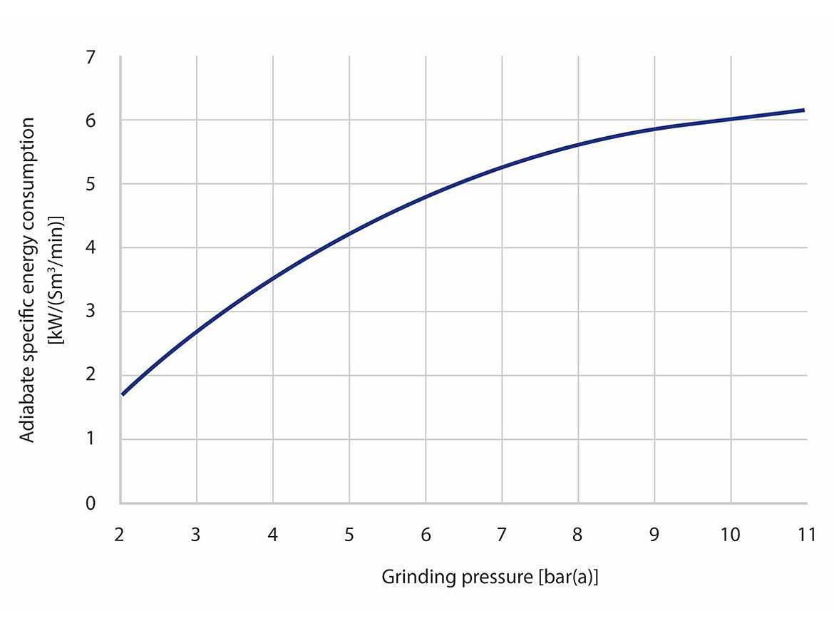
To disperse such bulk materials, lower grinding energy levels are enough in most cases. As a result, a high grinding pressure is no longer a “must” for the jet milling process. The higher the grinding pressure, the lower the efficiency of compressed air generation (Figure 1). Grinding pressures of 6 bar(g) require approximately three times more specific energy compared to a 1 bar(g) process. The necessary technology of the blower/compressor equipment also becomes more complex with rising pressures. The use of excessive jet milling pressures leads to high investment and operating costs.
The ideal pressure level must be determined individually for each product. For limestone, it should not be less than 4 bar, but the majority of LDP can utilize significantly reduced pressures. Some of them can still be processed below 1 bar(g). Therefore, simple and cheap rotary piston blowers can be used.
Some exceptional LDP require higher pressure levels for an efficient dispersion. Table 1 shows a comparison of graphite grinding processes based on the same capacity and a desired final fineness of 4.2 µm (dV50).2 Column A is based on a low-pressure process and B is running in a high-pressure mode.
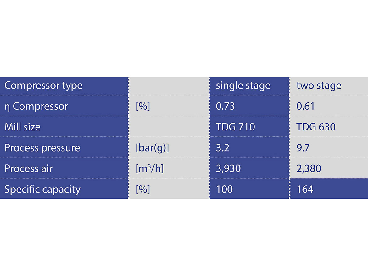
Even with a smaller mill size and a compressor efficiency reduced by ~12%, the grinding under high-pressure condition shows a specific capacity increased by ~64%. Hosokawa Alpine’s jet mill TDG can achieve even finer graphite qualities down to 2.5 µm (dV50) even on the biggest mill sizes.
Feeding Zone: A Single Powder Pump Replaces Feeder and Gate
Due to the low settling velocity, problems can arise with the normally used gravity dosing concept. One of the first jet mills had a material inlet placed below the grinding zone (stuffing screw). Reactivating this idea allows capacity increases of up to 10% for several LDP.
When the feed materials show a high fluidity after aeration, pumps can also be used as feeders instead of dosing screws. The typical combination feeder and gate can be replaced by a single powder pump.
Grinding Zone: Deceleration Speed and Hold-Up
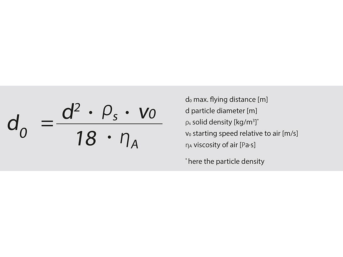
High particle porosities lead only to low momentum, and in combination with the movement inside a viscose media (air), the attainable flight distance is quite small. Due to the low apparent density, the stopping distance (see equation in Figure 2) for a 5 µm diameter SAS particle with a starting speed of 500 m/s is less than 1 cm. The corresponding stopping distance for a dense limestone particle is close to 10 cm.
These small linear momentum levels have an influence on the energy transfer inside a jet mill and, considering the normal “limestone-laws”, can only lead to an inefficient grinding arrangement.
Figure 3 depicts a CT-scan of a Hosokawa Alpine AFG/TDG jet mill. The three nozzles (blue) are injecting the compressed air (white) to the center of the mill (yellow). The above-mentioned effect means that the LDP particles have lost their kinetic energy at the focal point. As a result, the particles are only mixed and not ground.
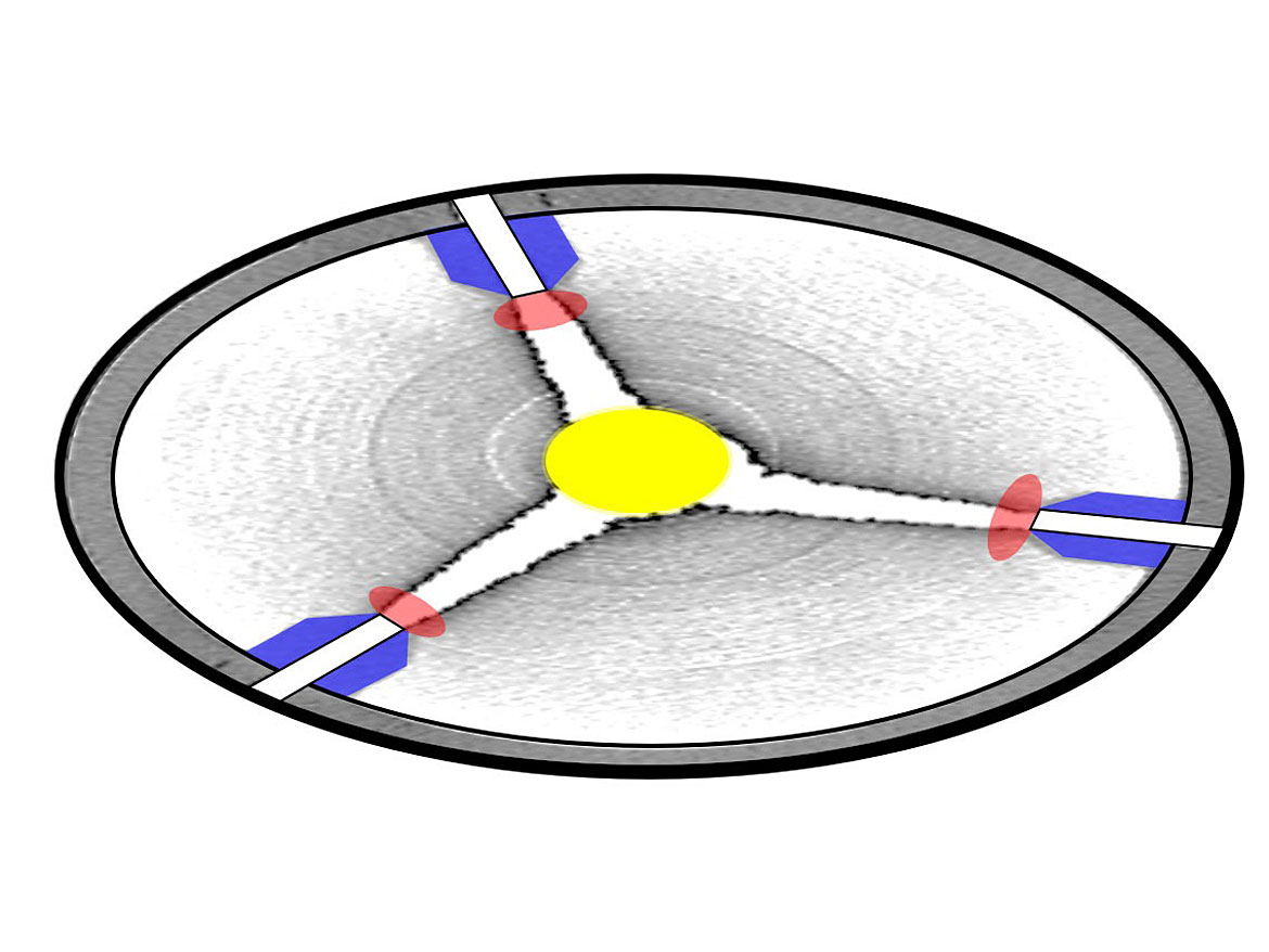
For denser materials, up to 30% of the grinding work can take place in the center. The remaining 70% are transferred in front of the nozzle, where the highest speed levels are located (red areas). LDP will receive almost 100% of the energy in the red areas. Ignoring the equation for the “ideal” nozzle distance and using an optimized position can increase the capacity by up to 10%.
It is not easy to determine the hold-up for fluffy materials inside the mill, but this is another important parameter of the process. As the material weight is quite small compared to the weight of the equipment, it is tricky to verify the real hold-up. Nevertheless, an optimized capacity can only be realized when the filling level is ideal, but the limestone experience here is misleading as well.
Transfer Zone: Housing Diameter without Any Influence
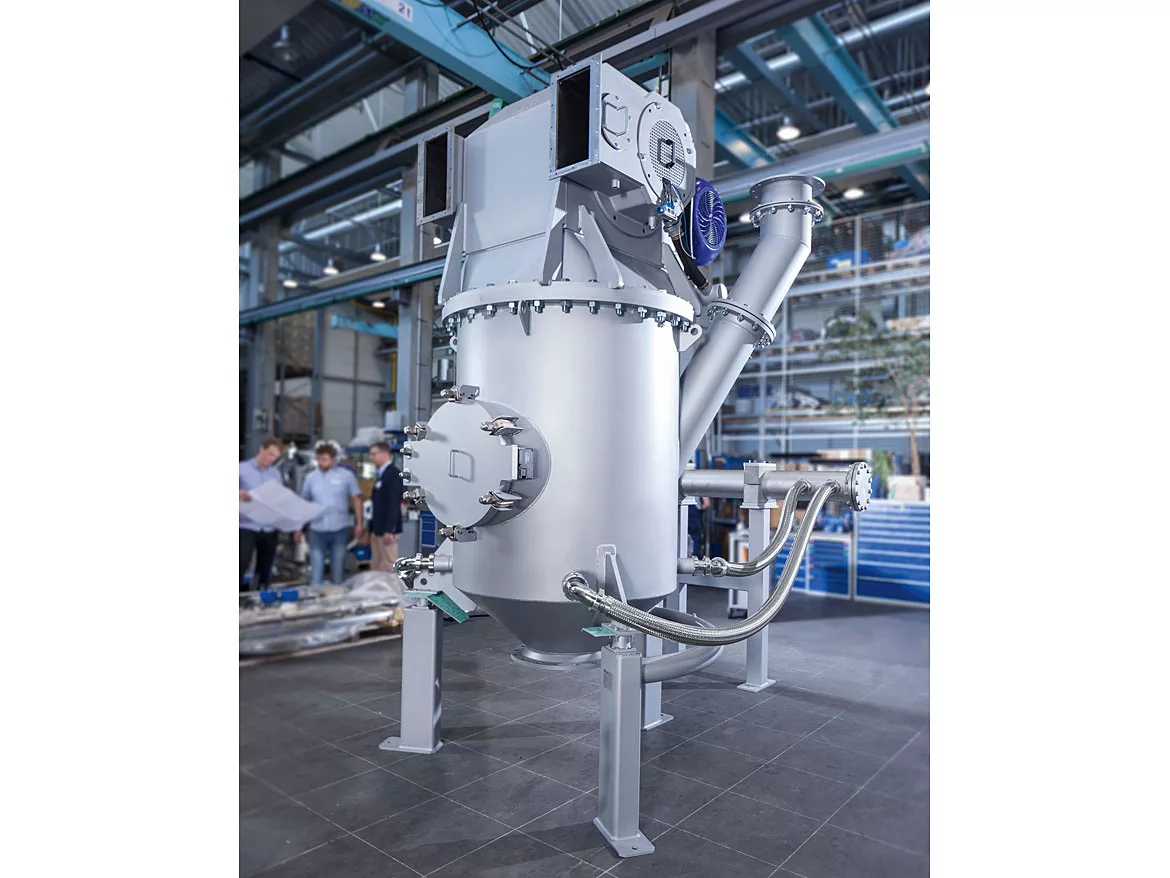
Figure 4 shows the 800 TDG with gas distribution unit. When the product leaves the grinding zone (A), a permanent upstream air flow transports the almost milled powder towards the classification area (C). Material that is fine enough can enter the classifier wheel and moves with the air into the separation filter. The oversized particles are rejected by the rotating field of the classifier wheel and fall down to the grinding zone again. This up and down movement in zone B is an essential part of the process and has also been investigated. To test various upstream velocities, various housing diameters for zone B have been installed. As expected, there was no influence to detect.

Classification Zone: Classifier Wheel and Control Parameters
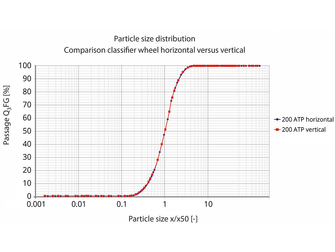
Regarding the wheel shaft, there are two general classifier arrangements available on the market: Either the wheels rotate around a vertical or a horizontal axis. As Hosokawa Alpine manufactures both types, it was easy to compare the horizontal shaft (AFG jet mill) and the vertical shaft (TFG jet mill). As was to be expected, the results are 100% comparable as far as fineness, capacity and efficiency when LDP are concerned. Due to the less complex construction, the tests were continued with the horizontal shaft arrangement only. Figure 5 shows a comparison of the particle size distributions between AFG and TFG.
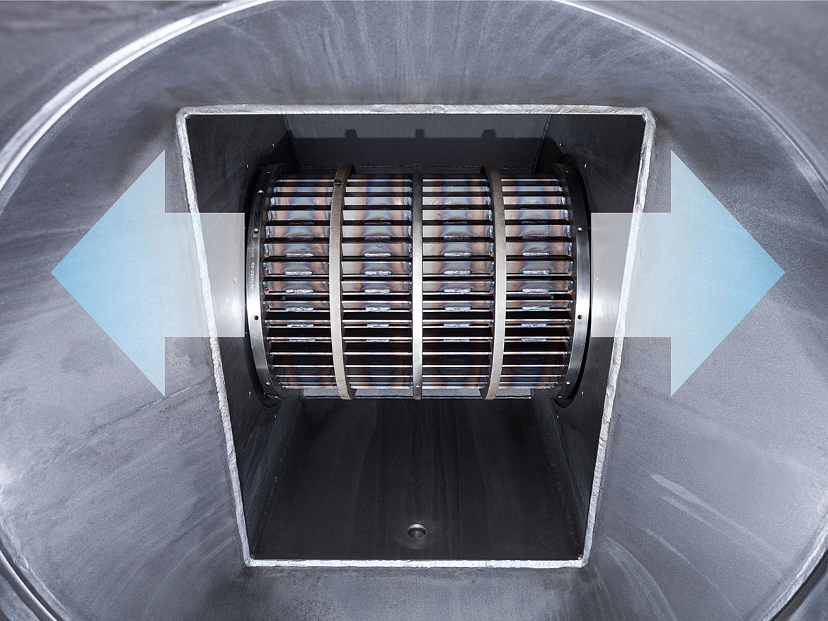
The main bottleneck of the milling process of LDP is the classifier wheel. The dispersion/de-agglomeration happens quickly, but the produced product must be able to leave the process just as fast. Therefore, the TDG wheel design was tested, which allows for higher capacities. A bigger length/open surface and outlets on both wheel sides limit the flow speeds and reduce the wear even with a doubled capacity (Figure 6).
The preferred finenesses for LDP are significantly less than 10 µm (e.g. carbon black, graphite, talc or silicas). When using normal classifier wheels, the necessary running speeds are close to the limit, resulting in a high pressure loss. A special design of the wheel blades allows an improved selectivity and fine cut points at significantly reduced wheel speeds. This will save energy and at the same time leads to very fine particle sizes below 1 µm (dV50). The achievable fineness is thus on a par with grinding processes using superheated steam.
A process control of jet mills by the mass flow (via mill weight or classifier power) is almost standard, but both concepts usually do not work in combination with LDP. For this reason, the process control parameters should be independent of the product mass to ensure maximum process stability. For LDP, the jet mill TDG uses an easily detectable value to control the optimum feed level. Any process deviation will be detected immediately and leads to an automatic countermeasure or alerts the operator.
Product Separation by Filtration
After milling/classifying, the product must be separated from the air stream. Cyclones usually do not work with most LDP, so filtration is the remaining option. With the used control parameters, a fine-tuning of the interaction of mill and filter is possible, and the filter-surface loads can exceed the recommended values in most cases. Finally, this also allows for reduced filter surfaces and filter housings. For LDP filters, the following aspects are mandatory:
- inlet below the filter head plate;
- no direct flow towards filter hoses;
- filter hoses equipped with membranes;
- steep wall angle for collecting hopper;
- sufficient outlet diameter.
Summary: Modifications and Adjustments Necessary for LDP
The investigations described finally lead to a modified mill type (AFG → TDG), and a selection of helpful adjustments and optimizations for processing of products with low densities. These include:
- energy saving by optimized grinding pressures;
- doubled capacity on same mill size (AFG → TDG);
- enabling of fine cut points;
- capacity increase by special feeding arrangement;
- capacity increase by modified nozzle set-up;
- smaller filter size.
The successful results described have now been transferred into a new plant concept. The TDG with the optional LDP-package offers all the tested options.
The 400 TDG used for this investigation is available in the test center in Augsburg. All options and modifications described (and even more options) can be installed and combined to determine the improvement potential for each product.
For more information, visit www.hosokawa-alpine.com. This article has also been published in Chemietechnik Magazine (October 2021) and in PPCJ (October 2021).
References
¹ Luckenbach, F.A.; Wolfenden J. United States Patent No. 238044, application out of 1880.
² Analyzed with Malvern Hydro in water
³ Rumpf, H. Beanspruchungstheorie der Prallzerkleinerung. Chemie-Ingenieur-Technik 5 (1959), S. 323 – 337 (Changed characters of English version)
⁴ Strobel A.; Köninger B.; Romeis S.; Wirth K.E.; Peukert W. Impact Comminution in Jet Mills. In: Stefan Heinrich (ed.): Dynamic Flowsheet Simulation of Solids Processes, Springer International Publishing, 2020, p. 305-347.
Looking for a reprint of this article?
From high-res PDFs to custom plaques, order your copy today!


