Next-Generation Paint Robots
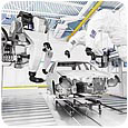
A paint cell with four robots (Dürr EcoRP E 32).
Robots designed specifically for the paint industry have been used worldwide since 1998 and have proven their performance under full production conditions. Recently, a second-generation paint robot has been developed specifically to facilitate the replacement of older paint machines in existing paint cells. The newest robot requires fewer booth modifications and can be installed and commissioned in less time compared to earlier robots. When used in greenfield installations, shorter booth lengths are possible, combined with a reduced capital investment and lower energy costs.
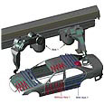
Figure 1. All axes allow significant flexibility in generating paint paths.
Robot Design
The newest paint robots are composed of either five or six movement axes arranged on a traveling axis. All axes allow significant flexibility in generating paint paths, which prevents overspray contamination and also provides a flexible work envelope on both horizontal and vertical surfaces when the painting task must be reassigned to another robot in case of a robot failure (see Figure 1).The paint atomizers are attached to each robot arm with two different wrists using either two or three movement axes. A 140-degree hand axis with an internal diameter of 75 mm is suitable for either rotary or air atomizers, while a 90-degree epoxy hand axis is used exclusively for rotary atomizers. A hollow wrist design has been optimized to allow for the best routing of hoses in the wrist, along with minimum hose torsion and bending stress.
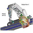
Figure 2. The application components and control valves are integrated into two robot arms.
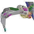
Figure 3. Cables (red) and hose cat racks (dark green) in the robot run through the “neutral axis.”
All cavities in the housings and arms of the robot are continuously purged with air to prevent the formation of an explosive solvent/air mixture. The control for this purging system is integrated into the robot. Purging of the carrying construction (gantry) of the robot is not necessary, which drastically reduces the purging time compared to earlier robots.
Digital servo-motors conforming to ATEX/UL standards drive all movement axes, as well as the application technology. Patented automatic mastering of the robot’s main axes (1, 2 and 3), as well as the traveling axis, allows the reference positions of the axes to be set simultaneously for all axes within minutes.
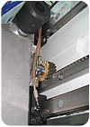
Figure 4. The traveling axis is propelled by a rack-and-pinion drive located inside the housing of axis 1.
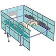
Figure 5. Exterior installations require one bulk head connector plate to be installed per booth side to allow the cables and hoses to run through the booth wall.
Installation
Booths that are at least 4.5 m (14.8 ft) wide can take advantage of the new robot technology. The system is integrated into the spray booth by vertical columns that can be located either inside or outside of the booth, depending on the booth conditions. Interior installations require no modifications to the booth wall, while exterior installations require one bulk head connector plate to be installed per booth side to allow the cables and hoses to run through the booth wall (see Figure 5).Depending on the project conditions, the traveling axis rail can be mounted to the support beam anywhere from 100 to 2300 mm (4 to 91 in.) above the booth grating level. Installing the rail at approximately 1.9 m (75 in.) or higher allows for an unobstructed view into the booth, along with improved booth airflow.
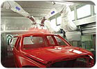
A next-generation robot (Dürr EcoRP E 33) paints pickup cabs at DaimlerChrysler in Saltillo, Mexico.
Future Advances
One of the first installations of the newest-generation paint robots was EvoBus in Ulm, Germany, which uses two robots to automatically apply primer to buses in an existing booth. Similar paint robots have also been installed in Mexico and the U.S., and additional projects are planned or already under way in Spain, England and Korea.Companies that have installed the new paint robots have realized significant labor, material and energy savings. For example, at DaimlerChrysler in Saltillo, Mexico, two basecoat paint application stations with machine technology and a total of 20 atomizers were replaced by eight paint robots. The robots are attached to traveling rails at a height of 1.9 m (75 in.), which allows them to paint the pickup boxes while providing an unobstructed view into the paint zone. The reduction in the number of atomizers alone has provided considerable material and energy savings.
Additional advances in robot technology are being pursued, some of which are expected to be available later this year. For example, an opener manipulator based on the same design and a clean-wall alternate for the traveling rail are being developed to minimize the possibility of contamination and improve paint process flexibility.
As companies continue to look for ways to increase productivity and reduce labor costs, robots will undoubtedly become an increasingly important component of modern finishing operations.
Links
Looking for a reprint of this article?
From high-res PDFs to custom plaques, order your copy today!


