E-Coat Color Control
The majority of electrocoat products on the market today are used as primers, many of which are meant to be topcoated. However, numerous color controllable electrocoat products exist that are both aesthetically pleasing and durable, and can be used as the final paint film on a coated part. Understanding the factors that affect color in electrocoat paint is critical to optimizing and controlling appearance, as well as maintaining a match to the color standard.

Figure 1. Simplified L*a*b* plot.
Defining Color
What is color? According to Webster’s Dictionary, color is defined as “a phenomenon of light or visual perception that enables one to differentiate otherwise identical objects.” While the human eye can distinguish somewhere between one and 10 million different shades of color (depending on which reference is consulted), a scientific method for determining differences in colors has been established that has helped standardize color perception and quantify differences in color between objects. Colorimetry, the science of color measurement, provides the “rules” of color measurement and is used widely in science and industry to express color in numerical terms.The first system of color organization was developed by Albert Munsell, an artist who taught at the Massachusetts Normal Art School from 1881 to 1918. His system was based on the premise that color is three-dimensional and that the three dimensions form a color space, which he depicted visually using equally-spaced color samples. To assign numerical values to colors, Munsell used notations to describe color in terms of hue, value and chroma:
- Hue: The attribute of color that distinguishes red from blue from green, etc. There are five principle hues: red, yellow, green, blue and purple; and five intermediate hues: yellow-red, green-yellow, blue-green, purple-blue and red-purple.
- Value: Describes the darkness or lightness of a color. Dark colors have a low value and light colors have a high value; the range is from 0 (black) to 10 (pure white).
- Chroma: The difference from gray of a color. Chroma is also known as color strength, saturation, or intensity, and has a range of 0 (low intensity) to 20+ (high intensity).
Using the Munsell color notation, 5R 6/12 describes a color in the middle of the red principle hue with a value of 6 and a chroma of 12. The Munsell Color Order System has stood the test of time, and it continues to be used as the primary basis for defining color in the U.S.
In 1931, the Commission Internationale de L’Eclairage (CIE) in France made the first major recommendations regarding colorimetric standards, forming the basis of modern colorimetry. Colorimetry is based on the principle that the human eye contains receptors for the three primary colors (red, green, and blue), and all colors are seen as mixtures of these primary colors. In colorimetry, these three primary colors are referred to as x (red), y (green) and z (blue) coordinates, or tristimulus values. Instruments known as spectrocolorimeters are modeled after this theory, and they use three photocells as receptors to interpret color in a fashion similar to the human eye. The basic components of a spectrocolorimeter include a light source, viewing optics, three photocells matched to a standard observer, and an internal or external processor/computer, which is used to perform the calculations of color measurement.
While the x, y, and z tristimulus values are useful for defining color, they do not allow for easy visualization of color. In 1976, the CIE created mathematical equations to convert tristimulus value into meaningful color space values known as L*, a*, and b*. These equations are referred to as CIELAB, and they are widely used for color determinations today. The CIELAB equations are as follows:
L* = 116 (y/yn)1/3 -16
a* = 500 [(x/xn)1/3 - (y/yn)1/3]
b* = 200 [(y/yn)1/3 - (z/zn)1/3]

Color symbols.
The overall or total difference in color between a specimen and the standard, described in terms of L*, a* and b*, is known as Delta E or DE*. The term is derived from the German word for sensation, empfindung. DE literally means the difference in sensation. In mathematical terms, DE (always a positive number) is expressed as:
DE* = [(DL*)2 + (Da*)2 + (Db*)2]
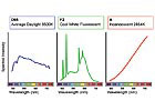
Figure 2. Standard illuminants.
While CIELAB math represents one of the most common set of equations used to determine color differences, other equations exist. Some examples include FMC2 equations, BFD equations, Hunter equations and M&S equations.

Effect of dry film thickness on color, white anionic acrylic.
Metamerism and Color Drift
It is important to note that color can be affected by the light source. For example, a blue object might be a noticeably different shade of blue or a different color altogether when viewed outside in the sunlight compared to the color when viewed indoors under fluorescent light. This phenomenon of color variations under different light sources is called metamerism. In 1931, The CIE established several standard illuminants for use in color determinations; these illuminants are tables of spectral energy intended to represent “real” light sources. The standard illuminants are D65 (average daylight), F2 (cool white fluorescent light) and A (incandescent or tungsten light), as shown in Figure 2.Illuminant selection usually depends on where the painted object is intended to be located. For example, the color of exterior products, such as agriculture or construction equipment, is usually tested with the D65 illuminant, while the F2 illuminant would be the logical choice for interior goods such as metal office furniture or air diffusers. For products that will encounter a variety of potential light sources, it is important to rule out metamerism in the pigment selection early in the formulation process.
In addition to choosing the math and the illuminant for your spectrocolorimeter settings, you must select the angle of the observer (2° or 10°), determine whether to include or exclude UV light and specular reflectance (gloss), and choose a large or small aperture, plus you must ensure that the unit is properly calibrated. All of these settings on your spectrocolorimeter can impact the results when testing the color of your parts.
For quality control purposes, specifications for color-controlled electrocoat pastes should be maintained at ± 0.3 or less for DL, Da and Db. This will keep the overall color difference between the batch and the standard at DE of less than 1.0, which is generally considered to be a production match. Since the color of electrocoat paint in an operating electrocoat tank usually tends to drift due to a variety of factors (preferential pigment deposition, color shifts caused by shear, settling due to poor agitation, etc.), the actual final color of a produced batch may vary greatly from the color standard. For example, it is typical for the color in anionic electrocoat paint baths to drift dark; therefore, production batches of color controlled anionic pastes are often sent out light to compensate for this drift.
The same logic applies if the final color in an operating electrocoat tank drifts in any direction; the color of the paste is adjusted to compensate for the drift. So if the color on-line is 2 units yellow compared to the standard, the paste is adjusted to be 2 units bluer; if the color on-line is 1 unit red compared to the standard, the paste is adjusted to be shipped out 1 unit greener. If you refer to the L*, a*, b* diagram in Figure 1, the preceding examples demonstrate that production batches and electrocoat paste formulas are adjusted to be the opposite color of the direction the color is drifting. Ultimately, these types of adjustments lead to minimal tinting on-line and a closer match to the color standard for the parts being coated.

Effect of cure temperature on color, gray cationic epoxy.
Operational Factors
In an operational electrocoat tank, many factors exist that can have an impact on the final color of the coated part. These factors include:- Oven conditions. Overbaking and/or poor oven exhaust will have a negative impact on color. The color typically will be dark and yellow if either of these conditions is present. It is important to ensure that the proper bake schedule is being used and that the oven has sufficient exhaust to minimize accumulation of fumes. Fumes that emit from the part during the curing process can be especially detrimental to lighter colored coatings, such as off-whites, beiges or light grays.
- Film build variation. Color shifts can occur with as little as 0.1 mil difference in dry film thickness (DFT). Light colors are affected by film build variations to a greater extent than dark colors.
- Rack loading. If large and small parts go through the cure oven simultaneously, the large parts can act as a heat sink, which can adversely affect the cure and color control of the lighter parts.
- Contamination. High levels of iron, ionic contamination, or problems with bacteria can all lead to yellowing of the paint film. Directing permeate into your waste stream can minimize ionic contaminants, but actions must be taken to completely eliminate any contamination source from your electrocoat bath.
- Bath parameters. It is important to keep the solids, pigment-to-binder ratio (P/B), conductivity, pH, and solvent levels within the recommended operating ranges to ensure proper color control. Maintaining the correct chemical balance in your electrocoat bath is critical to keep pigments and paint solids in suspension. Tanks that operate out of spec can experience poor solubility and other problems, which can lead to abnormal settling and “kick-out” or instability of paint solids.
- Substrate condition. Properly cleaned and evenly pretreated substrates lend themselves well to color-controllable electrocoat paint. Additionally, the type of substrate can affect color results, so if you coat multiple substrates out of the same electrocoat bath, you may see some color differences between them.

Effect of oven dwell time on color, gray cationic epoxy.
In Table 2, the data show that as the film build increases, the color shifts light, red and yellow. For this particular light-colored anionic acrylic product, DL (lightness/darkness) and Db (yellow/blue) change significantly as the film build increases. Light products tend to hide the substrate better at higher film builds, so the color results at lower DFT are affected by poor hiding over the pretreated substrate.
In Table 3, the data show that as the cure temperature increases, the color shifts dark, green and yellow. The tendency of epoxy paints to turn yellow during the cure cycle is exacerbated as the bake temperature increases, and is even more pronounced if oven exhaust fumes are present during curing. This is known as “fume yellowing.”
Table 4 shows that as the dwell time in the cure oven increases, the color shifts dark and significantly yellow. As in Table 3, cure effects are amplified for epoxy paints.
In Table 5, the color shifts light and blue as the bath solids increase.
In Table 6, the color shifts dark and red as the P/B ratio increases. Note that P/B effects on color are more pronounced in baths that operate out of spec low in solids, and that low P/B baths do not tend to hide the substrate well, especially for light colors.
The importance of maintaining an in-spec, contamination-free electrocoat bath cannot be overstated. Additionally, the substrate type, pretreatment quality and especially the cure conditions can all affect the color of the final paint film.

Effect of bath solids on color, green cationic acrylic.
Adjusting Color
While the software used by many spectrocolorimeters contains helpful color-matching programs that can assist with color adjustments, most of these programs require inputting copious amounts of information about the paste formulations and the specific kinds of tints that exist for your particular product. Much of this information can be obtained only by conducting numerous lab trials to determine average tint strength and the effects each tint has on various colors of products.Described below is a comparatively simple technique that can be used to determine the amounts and types of tints required to adjust color in an off-color electrocoat tank. Since this is a small-scale activity, conducting this work requires a laboratory equipped to electrocoat panels from a small container. Additional equipment includes a spectrocolorimeter, a film build gauge, and a small weighing scale.
The sidebar, “Tint Addition Tips,” provides some basic guidelines for adding tints. With these things in mind, the following method can be used to determine the appropriate amount of tints to add to an off-color electrocoat bath:

Effect of bath pigment-to-binder ratio on color, beige anionic acrylic.
- Begin by using your spectrocolorimeter to evaluate the color of a part that is representative of the ware being coated. Make sure that the unit is properly calibrated and that the appropriate settings are in place (math, illuminant, aperture, UV, gloss, etc.) Record DE, DL, Da, and Db. For example, let’s say the product is an off-white cationic acrylic with the following color results: DE/DL/Da/Db = 1.98/1.16/0.53/1.52 (light, red, yellow) at 1.0 mils DFT.
- Weigh out 1,800 grams of your electrocoat paint bath into an appropriate sized container and coat panels at the correct film build using the same substrate and pretreatment as the parts on-line, then bake several panels and evaluate the color. If the color of your lab coat-out is reasonably close to the color of the actual production part (within DE of 0.5 or less), then you are ready to start adding tints to your small paint bath. If the color is different than the part, then you should conduct troubleshooting activities on-line to determine the source of the discrepancy. The common culprit is the cure oven, as fume yellowing and/or over-baking are fairly common. If you are not able to resolve the color discrepancy, it may be necessary to use a correction factor to compensate for the amount of tints that need to be added.
- When you are ready to add tints to your lab bath, start with small amounts so you can determine the net shift in color. In this case, the color of the part is light, red and yellow, so the tint of choice is blue since it will drive the color dark, green and blue. Remember, the goal is to end up (numerically) in the center of Figure 1 to get the DE as close to zero as possible, so the tints to select are ones that will drive the color in the opposite direction of the DL, Da, and Db results. Let’s say that after a 1 gram addition into your 1,800 gram bath, the color results are DE/DL/Da/Db = 0.37/0.24/-0.28/0.06 (light, green, yellow) at 1.0 mils DFT. The net shift in color obtained from 1 gram of blue is 0.92 units dark (1.16 – 0.24), 0.81 units green (0.53 – (-0.28) (the color shifted green from 0.53 to zero, then beyond zero to -0.28, so you add the total shift)), and 1.46 units blue (1.52 – 0.06). This is a relatively simple example; some color adjustments require adding several different tints, each of which can potentially affect the total color shift in a different way. Add tints one at a time, then coat panels and check the color after each addition. Recording the net shift in color after each tint addition will help you determine which tints to add to your electrocoat tank to adjust the color.
- After you have adjusted your lab bath to an acceptable color match, calculate the amount of each tint to add to your electrocoat tank as follows:
Pounds of tint to add to the electrocoat tank = (total grams of each tint added to the lab bath / weight of lab bath) x weight per gallon of your electrocoat bath x total gallons of paint in your electrocoat tank
Going back to our example, if you have a 5,000 gallon electrocoat tank with a weight per gallon of 8.52 lbs/gal:
Pounds of blue tint to add to tank = (1.0g / 1,800g) x 8.52 lbs/gal x 5,000 gal = 23.67 lbs of blue tint
When it comes to actually adding tints to your electrocoat tank, it is a good practice to initially add half of the amount you think will be needed to adjust the color. This will enable you to “creep up” on the color without the risk of over-adding tints. Remember, you can always add more tints into your tank, but tints cannot be removed once incorporated. For proper color control, it is recommended that you conduct daily color checks on your production parts and keep a running log of tint additions along with the corresponding color shifts, as shown in Table 7.

Daily log of color results and tint activity.
Achieving Control
Color control in electrocoat paint can be achieved through a methodical approach of incorporating the appropriate amounts of various tints into the paint bath. These additions should be done in conjunction with controlling the color of the product as supplied, as many factors can cause the color to drift in an operational electrocoat tank.SIDEBAR:
Tint Addition Tips
DLIf positive, add black tint
If negative, add white tint
Da
If positive, add green tint or blue tint
If negative, add red tint
Db
If positive, add blue tint or black tint
If negative, add yellow tint
Also…
- It is difficult to make a red redder, a blue bluer, a green greener, etc. Higher tint quantities will be required.
- Light colors can be significantly affected by relatively small amounts of tints, and nearly all tint additions (except white tint and sometimes yellow tint) will drive the color darker quickly.
- It is difficult to lighten the color in most electrocoat baths, so expect to add a lot of white tint if the color of your electrocoat paint tank is dark.
- Adding tints may impact other color aspects as well as the one of interest. For instance, if the color of a part is too yellow (positive Db), the addition of blue tint will drive Db negative, but it will also drive DL and Da negative as well.
- Correct film thickness is critical for color measurements.
Looking for a reprint of this article?
From high-res PDFs to custom plaques, order your copy today!


