Improved Accelerated Weathering Protocol
A Crucial Tool in the Evaluation of Future Coating Systems and Processes

Accelerated testing of transportation coatings has been conducted for more than 50 years. The desire and purpose always has been to achieve a long-term service life prediction of a coating system using a short-term test in the laboratory. While all previous tests have provided some value to the industry and to those who have worked to develop coating technology, none of these tests actually provide a high confidence level in predicting the service life of today’s advanced coating systems. The advancement in coating analysis tools, improved coating technology and the increased complexity of coating application processes requires a more accurate test method than those that exist in the industry today.
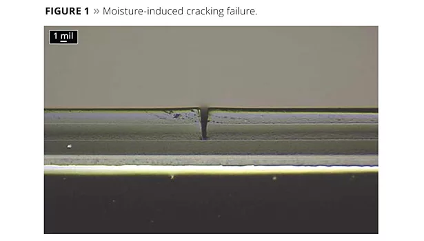
A new test protocol has been developed that greatly increases the correlation of service life prediction for transportation coatings in the laboratory to that of actual outdoor performance. The particular technical issues that led to the development of this new method were discovered with lab inconsistencies and actual service failures of automotive coating systems in certain environments between 10 and 15 years ago. Specifics of these failures have been discussed in previous articles,1 and an example of one of the failures is shown in Figure 1.
The automotive coating system shown in Figure 1 actually had some moisture sensitivity in the basecoat layer that led to this particular type of cracking phenomena. While coating formula changes were used to correct this issue, the current accelerated weathering protocol (SAE J1960, SAE J2527) for automotive coatings was not able to produce this defect. The reason for this is that the development of the SAE J1960 and J2527 standards were focused on producing defects that were only caused by UV light exposure.
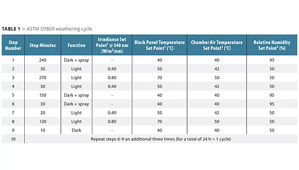
The new test method was based on 10+ years of collaborated research and testing with a number of companies. Throughout the 10 years of work, numerous publications were generated that detailed the flaws in the current cycle plus considerations in new cycle development,2 efforts to define and optimize in particular the moisture requirements,3 and the needs in running and maintaining the integrity of the test with accelerated weathering equipment.4 The new test is now an official test standard, ASTM D7869. The actual cycle is displayed in Table 1.
In this article, each step in the weathering cycle test method is discussed in detail, with the reasoning and data involved with the development of each step in the cycle.
Step 1
240 min Dark/Spray at 40 °C Black Panel,
40 °C Chamber Air, 95% RH
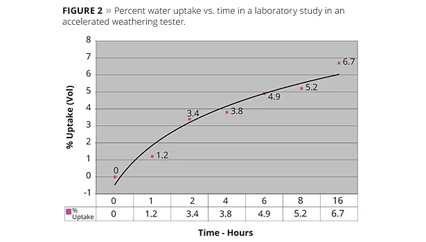
In previous publications5 it was shown that one of the biggest flaws in the J1960 cycle was the lack of sufficient water usage to provide mechanical and chemical changes in underlying coating layers. The overall importance of water in the accelerated weathering process has also been discussed in detail in previous publications.6 In looking at various transportation coating systems, there is a time/temperature relationship with the permeation of water throughout the coating layers. While the permeation rates and the amounts of water vary depending on the coating system, it is imperative that the accelerated test approaches the same degree of overall permeation as a worst-case scenario for outdoor exposure. Figure 2 is an example of a lab study done to optimize the time required for proper water exposure.
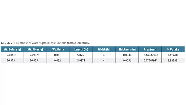
Based on data from actual outdoor testing, weather data and water-soak experiments, it was known that this particular coating layering system had a high percentage of uptake (approximately 5%/volume). Depending on the coating layering system and the chemistry of each coating layer, the water uptake values can range anywhere from slightly under 1%/volume up to 5%/volume. The typical method to calculate percent water uptake is shown in Table 2. The data in the table represent the percent water uptake of a common automotive solventborne coating system.
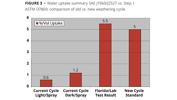
In summary for Step 1, Figure 3 depicts the expected water uptake for a particular coating system as compared to the worst-case scenario in a South Florida outdoor exposure. As seen in the chart, the previous and still-used standard SAE J1960/J2527 was deficient in water exposure.
Step 2
30 min Light at 0.40 w/m2/nm at 50 °C Chamber Air,
42 °C Black Panel Temperature
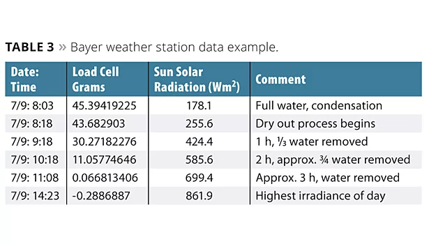
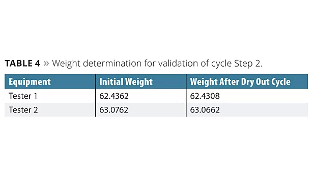
This step is designed to remove all of the water from the coating layers after the dark/spray cycle. As shown in detailed collection of weather data as provided by Bayer MaterialScience,3 it is seldom (<1% chance based on data from Florida 2004-07) that any significant levels of water remain in a coating film when the light irradiance reaches its maximum during a Florida summer day (Table 3). The reason that the black panel and chamber air temperatures are different is that the accelerated process is able to properly control within acceptable tolerance in the 40-50 °C range at the low irradiance. The lower irradiance in the test (0.40 w/m2/nm) is representative of an early to mid-morning light exposure, which is typical for the time period outdoors when the water is being removed from the coating layers. The time length of this step is kept at a minimum as it detracts overall from the acceleration of the test, but is crucial in the prevention of false negative results during the accelerated testing process. The weight determination for the validation of this cycle is shown in Table 4.
Step 3
270 min Light at 0.80 w/m2/nm at 50 °C Chamber Air,
70 °C Black Panel Temperature
This step is the main long light exposure step in the cycle. The ability to increase the irradiance from the standard 0.55 w/m2/nm used in SAE J1960/2527 helps to increase the acceleration by close to 50% over the forenamed test and actually still dramatically improve the overall accuracy of the test. A key in being able to increase the irradiance is the implementation of a new and more accurate daylight filter.7 The SPD of this new filter combination is a much better match to the SPD of natural sunlight (Figure 4).
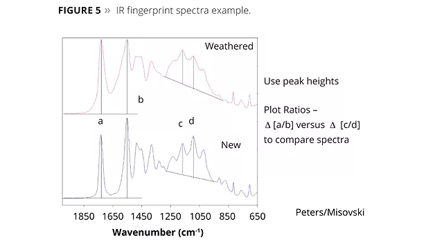
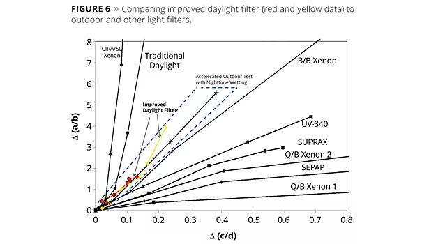
Using the improved filter also leads to a better match of the chemistry of the failures in the accelerated test compared to the actual outdoor exposure. The fingerprint region of an infrared spectrum can be used to compare the specific changes in chemical bonding in the coating system (Figure 5). Looking at specific peak ratios of the IR spectra can help determine if the same reactions are taking place at the same rate. In comparing peak ratios (Figure 6) of various filter combinations, the data shows that the improved daylight filter provided a closer match to the type and rate of chemical degradation reactions that the same coating sees outdoors. While it may be possible to use even a higher irradiance than 0.80 w/m2/nm in an accelerated test (it has been show that concentrators at four suns exposure is possible outdoors7), one needs to maintain the proper cycle relationships, and there are limitations to the ability of accelerated test equipment to maintain environmental parameters at higher irradiance settings. Also, the use of the new filter combination helps to provide more accurate color change and fade results than the current SAE J1960/2527 protocol.
Step 4
30 min Light at 0.40 w/m2/nm at 50 °C Chamber Air,
42 °C Black Panel Temperature
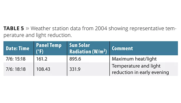
This step is exactly the same in the cycle as Step 2 but for a different reason. At this point there is no water uptake or moisture inside any of the coating layers. This step is intended to provide some stress relief, which would be similar to a coating system at the end of the day when the sun starts to go down prior to nightfall. This step also prevents any unusual mechanical failures that could occur when going from a high-temperature step to another dark/spray step in the cycle. Bayer weather station data demonstrates this in Table 5.
Step 5
150 min Dark/Spray at 40 °C Black Panel,
40 °C Chamber Air, 95% RH
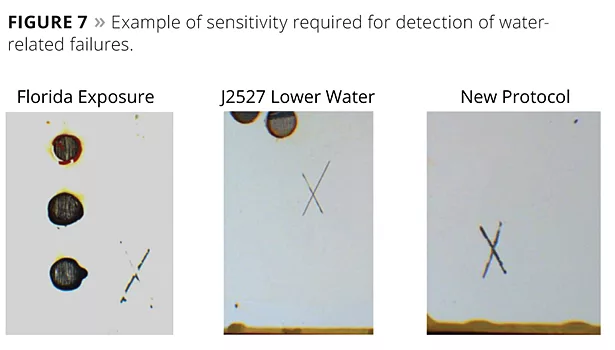
This step is for additional water uptake and exposure, which is necessary when considered with Step 1 to produce the magnitude of the water-related failures as seen in a South Florida exposure. As seen in Figure 7, a fine line exists with water in being able to detect even the slightest of adhesion failures, and without both water uptake Steps 1 and 5 the sensitivity of the test would be compromised.
With the shorter time in this step, we know from Table 1 that the overall water uptake is lower, but this would represent a condition of light to medium rainfall or condensation, which would be a fairly normal situation seen in a South Florida summer environment. The additional 30 min added to this step via Step 6 does help to slightly increase the coating water uptake (see below).
Steps 6-9
Mechanical Cycling Test Segment
As was properly designed in principle by the developers of SAE J1960/2527, the short test cycle with rapid changes in condition are important in detecting coating mechanical failures, i.e., lack of the proper viscoelastic properties for an outdoor test environment. An obvious fact is that an outdoor coating system undergoes at least one mechanical (diurnal) cycle every day as the temperature, humidity and moisture levels change. In a typical two-year exposure outdoors, that would mean at least 730 mechanical cycles would be needed, and the real facts are that there are likely over 1000 mechanical changes that a coating system sees in that time period. While it is not possible to accelerate the test in the laboratory to produce the same number of cycles, it is an important key to produce enough mechanical (viscoelastic) changes in the coating system to replicate defects seen in the outdoor test environment. These steps are repeated three times in the test protocol, which produce a sufficient number of mechanical cycles to reproduce the typical coating failures seen in actual service.
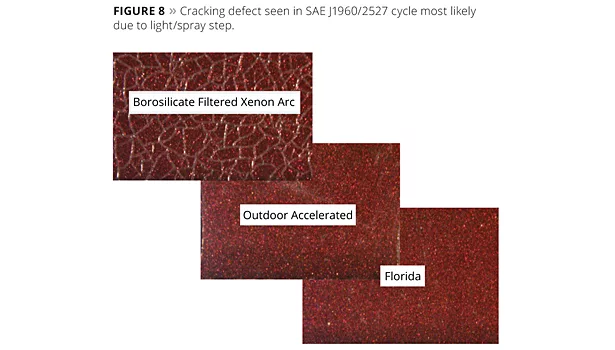
Note that there is no light/spray step in the new test standard as opposed to this type of step being included in SAE J1960/J2527. There are numerous examples of false failures with this type of step, particularly the presence of false cracking defects, as shown in this one example (Figure 8).
Step 6
30 min Dark/Spray at 40 °C Black Panel,
40 °C Chamber Air, 95% RH
As mentioned above, the first time Step 6 is implemented in each 24-h cycle it combines with Step 5 to provide a longer water exposure step. When this step is repeated twice more in the 24-h cycle, the step represents a light rainfall or condensation, and in the 30-min time period in this step there is no significant water exposure other than in the top coating layer, and all that occurs in this step is a slight mechanical change. Therefore, there is only a minimal contribution to migration of materials and any water-related chemistry and delamination failures created in this step.
Step 7
20 min Light at 0.40 w/m2/nm at 50 °C Chamber Air,
42 °C Black Panel Temperature
Again, this step is designed to remove all the water from the coating layers before the start of the light cycle. Since the water exposure from Step 6 combined with Step 5 would be 180 min as opposed to 240 min in Step 1, the time required for the water removal is slightly less.
Step 8
120 min Light at 0.80 w/m2/nm at 50 °C Chamber Air,
70 °C Black Panel Temperature
While this step adds to the total UV exposure and acceleration of the test cycle, the primary purpose here is to induce mechanical stress into the coating system. While the dark/spray step causes mechanical expansion of the coating due to water uptake, in this step there is a transition into a thermal expansion that lasts for only a short time compared to Step 3, which is over twice as long in time duration. The short time duration of Steps 6-9 is necessary to determine if the viscoelastic properties of the coating system are designed to withstand the stresses caused by rapid environmental changes.
Step 9
10 min Dark at 40 °C Black Panel,
40 °C Chamber Air, 50% RH
This last step is designed to be a total relief point where there are essentially no stresses applied on the coating system. This is a fairly normal daily occurrence outdoors. While it would be desirable to have this step at a lower temperature, such as 25 °C, there are difficulties in reaching that low a temperature in the short time allotted for this step. While arguments can certainly be made for a longer time duration for this step, it appears that just a momentary stress relief is sufficient to prevent any unusual failures through this portion of mechanical cycling.
Conclusions
The methodology in this new cycle (now published as ASTM D7869) applies not only to automotive coating systems with steel and plastic substrates, but can also apply to aircraft coatings as well as coatings for other industries where outdoor weathering and durability is required. Some of the automotive OEMs are in the process of adopting the standard into their specification testing requirements.
References
1 Boisseau, J.; Pattison, L.; Henderson, K.; and Hunt, R. PCI, June 2006.
2 Nichols, M. Considerations in Designing Accelerated Weathering Tests. SAE World Congress, April 2009.
3 Boisseau, J.; Pattison, L.; Henderson, K.; Hunt, R. Coatings Tech., September 2008.
4 Boisseau, J.; Pattison, L.; Nichols, M.; Misovski, T.; Henderson, K.; Quill, J. Understand, Measuring, and Optimizing Water Usage in Xenon-Arc Accelerated Weathering of Automotive OEM Coatings. FutureCoat, October 2008.
5 Fitz, T.; Boisseau, J. Understanding the Impact of Water in Natural Weathering by Separation of Variables. Coatings Tech Conference, March 2011.
6 Boisseau J.; Pattison, L. The Importance of Water in Weathering. PCI, November 2010.
7 Nichols, M. Refining Accelerated Weathering Testing to Anticipate Outdoor Exposure Performance. 2010 International Symposium on Natural and Accelerated Weathering Tokyo, Japan.
The Weathering Team
The author would like to recognize the entire team that worked together for as many as 10 years on the testing and adoption of this standard. The team includes Lynn Pattison, Don Campbell and Don Barber from BASF; Jacob Zhang and Matt McGreer from Atlas; Karen Henderson and Don Smith from Bayer; Jill Seebergh and Doug Berry from Boeing; Jeff Quill from Q-Lab; Todd Fitz and Nicole Verweys from Honda; and Tony Misovski, Cindy Peters and Mark Nichols from Ford.
Looking for a reprint of this article?
From high-res PDFs to custom plaques, order your copy today!


