Scalability of Agitated Bead Mills
From Lab to Production Scale

Coatings manufacturers spend a lot of time researching and choosing the best raw materials and milling equipment for their products due to the large variability of products in terms of components, viscosities, particle size distributions (before and after the dispersing/milling process), and other properties. Very often the first stage of this work is done on lab-scale mills. This research work is necessary for reliable scale up from the lab to the production scale. Hence, milling equipment manufacturers have developed flexible lab mills, with exchangeable process zones with a high similarity to the production mill types.
This article addresses typical scale up procedures and potential challenges. The question of the smallest possible process zone size, which is important for efficient R&D work, is also discussed.
Introduction
R&D personnel prefer to use the smallest equipment to develop formulations in order to save on raw material cost as well as reduce the time needed to prepare samples and clean the equipment. However, predicting production parameters for a large-scale production mill is impossible when the R&D tests have been conducted on a lab mill that is too small. Further, mill manufacturers are limited by several geometric and physical facts in designing the mills smaller and smaller.
A suitable way to scale up is to perform the large number of screening tests for a feasibility check of formulations with some miniaturized lab equipment,1 and then to perform scale-up tests with the most successful formulations on a lab mill that is suitable for a reliable scale up.
Scaling Agitated Bead Mills
Often mill suppliers launch their first mills in production size before they develop and launch lab mills. It is more of a challenge to scale down a machine than to scale it up.
For a scale down, the mill designer has to accept several geometric and physical limitations and constants that cannot be changed. The important parameters are:
- Particle size (particle size distribution) before milling, dP;
- Diameter of the grinding beads, dgb;
- Dimensions of the agitating tools (discs, pegs);
- Diameter, dgc, and length, lgc, of the milling chamber;
- Distance between rotor and stator of the milling chamber, Sgc;
- Rotor speed, vr; and
- Specific cooling surface, Sc.
Grinding Beads and Particle Size
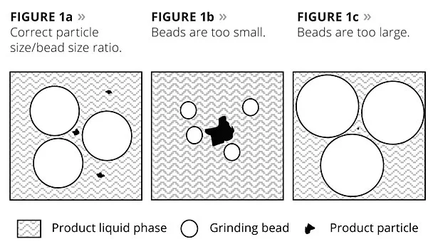
Most important for a good milling effect is the correct ratio between the size of the grinding beads and the particle size (Figure 1a), which has to be nearly constant. If a mill has to be scaled down it is not possible to also reduce the particle size (before milling) and the diameter of the beads. Particle size before milling is strictly constant as a part of the milling task and, as a consequence, bead diameter is constant as well. The reason for this is that beads that are too small will not be able to reduce the particle size (“destroy” the particle) because of their small bead mass. A small bead will only knock on the particle without breaking it (Figure 1b). Further, the bead package could start to act as a filter and accumulate particles and agglomerates in the mill. Consequently, the mill will block. In the opposite situation, if the beads are too large the probability of a crash between the beads and the particles falls drastically (Figure 1c). In both cases the milling effect will be poor.
Bead Size and Milling Chamber Dimensions
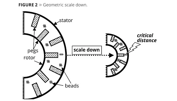
If we start to scale down a mill chamber geometrically we will soon hit some critical limits. The first will be the distance between the end of the pegs and the opposing chamber wall. A minimum rule exists – this distance has to be at least three times larger than the diameter of the beads. If we undercut this factor we run the risk of jamming and destroying the beads. Figure 2 shows a large process chamber where this rule is fulfilled, and a scaled down chamber where the situation becomes critical because the rule is no longer fulfilled. Reducing the bead size is not a solution because the ratio between the particle size and the bead size has to be constant during scaling up or down, and the particle size (before grinding) is constant as well (given task). If the goal is to reduce the size of the grinding chamber, as shown in Figure 2, we have to reduce the length of the pegs. This can cause a slightly different behavior of the mill in terms of the intensity of the energy input into the mill chamber. This difference can normally be handled because the user who is responsible for the scale up will build up knowledge within a short time.
Milling Chamber Dimensions
A typical rule for scaling agitated bead mills up or down (e.g., full-volume mills) is to keep the ratio between the main dimensions (length lgc and diameter dgc) of the milling chamber constant:
(1)
and, therefore
(2)
Further, it is necessary to keep the flow velocity of the product through the mill (vsl) proportional to the cross-sectional area (Agc) of the mill. This is very important for the identical distribution of the grinding beads within the milling chamber. Depending on the type of milling chamber and its design the limits of a scale down will be reached sooner or later.
Distance Between Rotor and Stator
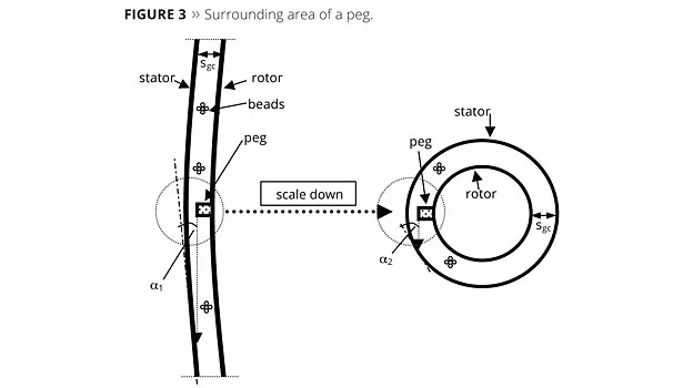
The mill designer tries to keep the distance between rotor and stator wall (Sgc) and the size of the pegs constant as long as possible during the scale down of a mill. This allows the local energy input per volume to remain constant as long as possible. But, as Figure 3 demonstrates, the surrounding area of a peg changes during the scaling procedure. The hypothetic trajectory of a bead accelerated by a peg becomes much shorter, and the angle (a) of the trajectory to the stator wall becomes larger if the diameter of the milling chamber is reduced. This will influence the motion behavior of the whole bead package.
Rotor Speed
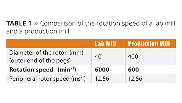
The rotor speed (often measured as the tip speed of the rotor pegs, vr) determines the energy input into the milling chamber. If the dimensions of the mill are decreasing, the energy input can be kept constant over a certain range of the mill dimensions by increasing the rotation speed (Table 1). Of course some additional speed variation may be necessary to find a stable operation point. It is important to keep in mind that with increased rotation speed and, therefore, an increased angular speed, other effects can occur.
Specific Cooling Surface
During scale up or down of agitated media mills the process zone volume increases or decreases with the third power. The specific cooling surface of the process zone only increases or decreases with the second power. This means that the cooling efficiency of a large mill is often smaller than that of a smaller mill. An exception to this rule is a miniaturized lab-size mill where the small design no longer allows cooling channels. In this case the small mill will have a lower cooling efficiency compared with a larger mill.
The product outlet temperature can change with scaling up or down of agitated bead mills. There are only a few types of agitated bead mills that have been designed to keep the specific cooling surface constant over several mill sizes, but this exception is also not valid for the miniaturized mills of these series.
Logical Consequences
A mill designer has to consider several rules and limitations for scaling up or down an agitated bead mill. It becomes clear that a certain mill type cannot be scaled in any order. Going beyond the limitations breaks some of the rules, and a different behavior of the down-scaled mill will result. In this case a scale up of a milling process from such a miniaturized mill to a production size mill will not be very reliable.
Scale Up of Milling Processes
First of all, there is no general scale-up method available. Scale up of milling processes can depend on:
- Product type (e.g., viscosity);
- Milling task (deagglomeration or true grinding);
- Mill type, with its properties;
- Mill operation type (single pass, recirculation); and
- Mill size differences.
Mill suppliers know many scale-up methods for milling processes and are able to help users scale up their processes or develop their own method. Often mill users are themselves very creative in developing scale-up procedures. This is very important because of the high influence of the milled product on the milling process.
The following section discusses some possible methods for scaling up of milling processes. Comprehensive theoretical disquisition with a complete set of formulas can be found in References 2-6.
Method of Constant Mass Specific Energy
For many coating and ink products with moderate viscosity, and for some mill types that can be used for these products, the method of constant mass specific energy, Em, is a suitable scale-up method because product quality usually depends on the energy input:
Quality = f (mass specific energy). (3)
The main assumption of this method is
Em ≠f (mill size). (4)
For a single-pass operation of a mill, Em is defined as:
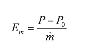
(5)
where P is the total power consumption of the mill; P0 is the idle power (power consumption of the empty mill); and .mis the throughput rate of product through the mill. Em can now be easily calculated from the measured data from a pilot mill. If there is a larger mill available, .m can be estimated for this large mill under a set of assumptions and some geometric proportionalities.
The main assumptions are:
- Lab mill and production mill have the same design;
- Same bead size and bead material (same density);
- Same bead filling degree;
- No bead compression; and
- Similar specific flow through cross-sectional area.
For a single-pass operation, the throughput rate for the production size mill is
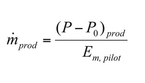
(6)
where the index prod means production mill and pilot means pilot/lab mill.
For recirculation mode operation, the appropriate equations are:
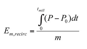
(7)
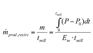
(8)
tmill = milling time.
It is self-explanatory that these equations will no longer be valid if, for example, the lab mill and the production mill are not the same type and design (or series), or if bead size or bead material or filling degree changes, or if an increased viscosity causes bead compression. In addition, a large change in the rotor speed can change the conditions in the mill too much for the above equations to be valid.
Sometimes, if some of the mentioned assumptions are not completely fulfilled, a correction factor to the mass specific energy can help to improve the prediction for the production mill. This factor can be developed experimentally and can be improved with experience.
Method of a Constant Factor Between Different Mill Sizes
Some products have to be scaled up by throughput rate factors. As soon as the viscosity is on an increased level, bead compression cannot be avoided. Further, some products can be milled perfectly under a controlled level of bead compression. In these cases the methods discussed earlier will not work.
The method of a constant factor between different mill sizes is not based on theoretical calculation but on the experience of the mill manufacturer, and can be improved and specialized by the user of the mill.
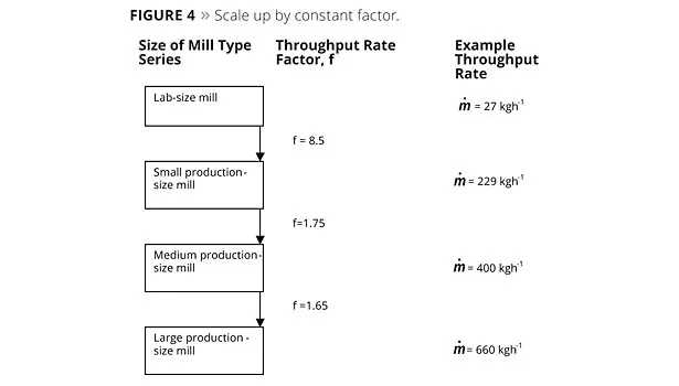
Within a certain mill type series the throughput rate of the product through the next machine size at the same quality level can be calculated by a constant factor (Figure 4).
Also for this method it is indispensable to keep some variables constant:
- Lab mill and production mill have the same design;
- Same bead size and bead material (same density);
- Same bead filling degree;
- Similar bead compression; and
- Similar specific flow through cross-sectional area.
In some cases this method has been used for different mill types. That means the lab mill and the production mill were not from the same mill series. To do this, a lot of experience is necessary. This is possible when a mill user has many different products, and when the user generates a lot of scale up data with these products.
A Typical Multifunctional Agitated Lab Bead Mill
All manufacturers of production mills also offer lab mills of the same design, which can be used for scale-up purposes. The volume limit for a geometrically downscaled mill chamber is approx. 0.5 to 1 L. Smaller chambers will usually have a more or less different shape. For miniaturized mills with chamber volumes of some mL or less, manufacturers of production mills are not the right partners. Suppliers of lab equipment can offer solutions for this.1
Figure 5 shows a typical lab mill that can be used for scale up of different mill types. The mill chamber can be exchanged and the drive of the mill can be turned from horizontal to vertical operation, depending on the mill type. There are more than 15 different chamber types and chamber type executions (e.g., different material, different steel types, different ceramic types, different polymer types) available that can be installed on the same machine body.
If a customer has different mill types for which lab process zones of the same supplier are available, the customer needs only one machine body and the corresponding process zones. The peripheral equipment such as pumps, product tank, piping and tubes can often be used for the different process zones. Sometimes different pump sizes or some additional sets of pipes and tubes are necessary, or can at least increase the flexibility of the complete lab installation.
Conclusions
Scale up of agitated bead mills is possible. Sometimes, especially in the case of minimized lab equipment, a two-step scale up is necessary. The scale up method is based on the product and the mill type used. Sometimes a suitable method for a reliable scale up has to be tailor-made for the application.
References
1 Juhnke, M. Accelerated Formulation Development for Nanomilling of APIs Using a Screening Approach; 6th International Symposium Wet Grinding and Dispersing 2009.
2 Stehr, N. Kleiner ist grösser. Qualitäts- und Wirtschaftlichkeitssteigerung von temperaturempfindlichen Produkten durch Perl-Mahlung bei hoher Leistungsdichte; FARBE&LACK 2001107, 7, S. 52/59.
3 Kwade, A.; and Stender, H.H. Konstantes Zerkleinerungsergebnis beim Scale-up von Rührwerksmühlen; AUFBEREITUNGS-TECHNIK(1998)39 Nr. 8, S 373/382.
4 Karbstein, K.; Müller, F.; and Polke, R. Scale up bei der Echtzerkleinerung in Rührwerkskugelmühlen; AUFBEREITUNGS-TECHNIK(1996)37 Nr. 10, S 469/479.
5 Stender, H.H. Diss. TU Braunschweig; Einfluss von Grösse und Bauart auf die Zerkleinerung in Rührwerkskugelmühlen, S. 174/179.
6 Kwade, A. TU Braunschweig; Zerkleinern und Dispergieren mit Rührwerkskugelmühlen, Kursunterlagen 2010.
Looking for a reprint of this article?
From high-res PDFs to custom plaques, order your copy today!
