Mechanism of Abrasion Resistance

Credit: Shamrock Technologies
Credit: Shamrock Technologies
Credit: Shamrock Technologies
Credit: Shamrock Technologies
Credit: Shamrock Technologies
Credit: Shamrock Technologies
Credit: Shamrock Technologies
Credit: Shamrock Technologies
In 1970, it was learned that a polytetrafluoroethylene (PTFE) micropowder, in combination with wax, greatly increased the rub resistance of printing ink. An early investigation of the mechanism was done by printing on a transparent substrate and rubbing with paper. The microscope was then used to study the appearance.
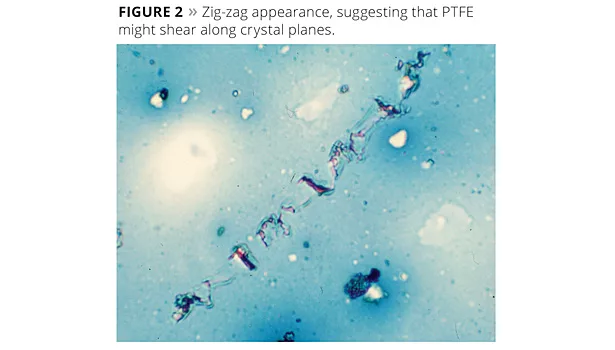
Some of the rub streaks caused by the paper fibers had the appearance of a flowing liquid, which was interpreted as the wax melting under pressure (Figure 1). Other streaks had a zig-zag appearance, suggesting that the PTFE might shear along crystal planes (Figure 2). It was thought that some of the properties were contributed by each mechanism.
Over the next 43 years, various combinations of wax and PTFE have been used in inks and coatings. Attempts to use incident light microscopy to better understand the mechanism have revealed little.
Polarized light microscopy is used to identify and characterize materials on the basis of their crystallinity. Wax can be distinguished from PTFE by the difference in their indices of refraction. To understand the present investigation, it will be helpful to have an overview of polarized light.
Polarized Light
Polarized light vibrates in only one plane. When passed through a second polarizer having a perpendicular vibration axis, the light is extinguished. For crystals other than those in the cubic (isometric) system, light passes at different speeds with different orientations. Some wavelengths are slowed down more than others. The combination of wavelengths that pass the upper polar produces interference colors, which depend on the retardation between the fast and slow rays.
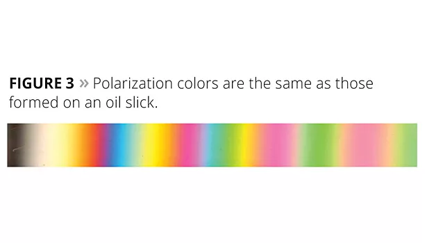
Examining a quartz wedge between crossed polars in polychromatic light produces a range of colors (Figure 3). At the thin edge of the wedge there is almost no retardation. All of the wavelengths of light are cancelled at the upper polarizer, resulting in black. With increasing thickness, corresponding to increasing retardation, the interference color changes from black to grey to white to yellow to red and then a repeating sequence of colors from blue to green to yellow to red.
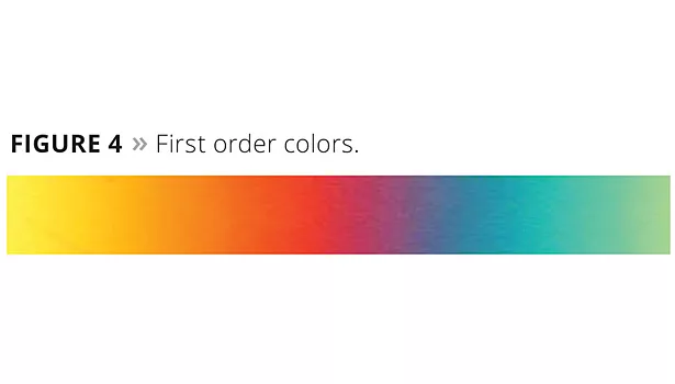
Figure 4 shows the “first order” colors. You see red in the middle, with blue and yellow to either side. These retardation colors are used to accentuate the appearance of crystalline material. A “retardation plate” can be added to the microscope’s optical system to help visualize crystallinity. This is how the wax and PTFE crystals are made to appear blue or yellow. What is seen without polarization as white light becomes red.
Understanding PTFE
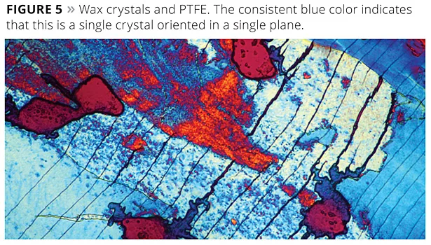
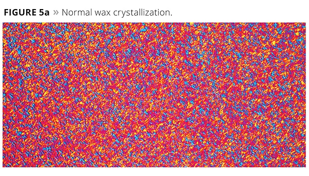
To further understand how PTFE and waxes work together, a pressure cell was developed. This device was capable of smearing wax and PTFE. Flow properties could be seen, but the apparatus was difficult to work with. Thinking that properties of materials change with temperature, much as they do with pressure, a slide was prepared by melting a combination of wax and PTFE on a hot plate. This was then placed on a cool surface and smeared as the wax crystallized. This resulted in the growth of huge crystals such as the one shown in Figure 5. Figure 5a shows the normal form of crystallization.
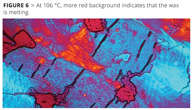
The slide was then heated on the microscope using a hot stage. As the temperature increased, more wax melted until only PTFE remained (Figures 6 and 7).
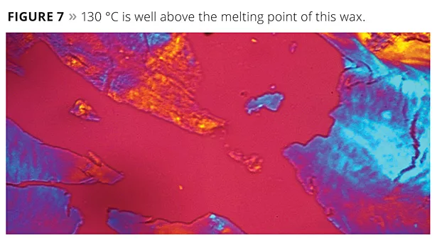
In Figure 7, the red background is caused by the added retardation. The background would be clear without this optical accessory. The blue and yellow/orange colors are the polarization colors of a PTFE crystalline film.
Since PTFE is the only solid material present when the wax is melted, it is shown that the original PTFE particles became a crystalline film. The width of the picture is half a millimeter, or 500 micrometers, and the original particle size of the PTFE particle only 5 microns.
Upon cooling, the wax also crystallized in a single crystallographic plane. It now becomes logical to conclude that the PTFE film served as the nucleation site for the crystallization of wax. It may also suggest that the crystal plane in which the wax is then oriented is the plane most effective at resisting abrasion.
Conclusion
It is known that the combination of wax and PTFE provides much better wear resistance than either one alone. This may be explained by the effect illustrated. Various forms of PTFE worked, some better than others. Waxes in the 100 °C to 120 °C melt point produced this effect to varying degrees. This approach to product development cannot substitute for application testing, but understanding the mechanism is a good step toward innovation.
Acknowledgements: Dr. Bin Chen for some of the microscope work, and John Vollmuth for the first investigation.
By Bill Neuberg, Chairman and Technical Director, Shamrock Technologies, Newark, NJ
Looking for a reprint of this article?
From high-res PDFs to custom plaques, order your copy today!


