Controlling Air Temperature to Improve Finish Quality

It has long been believed that air temperature has a significant impact on spray coating finish quality, primarily due to its impact on the viscosity of the atomized paint particles. Millions of dollars are spent each year controlling the booth ambient environment based on this belief. One of the things that has always bothered us about this concept is the degree of seasonal variation that coaters experience. If the ambient temperature is being held constant year-round, why is it still necessary to have a summer blend and a winter blend? Since seasonal variations are, by their very nature, temperature related, it seems there must be something else at work here.
Retrospective
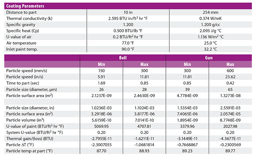
When we introduced our 2018 paper, “Guns or Bells, How Do I Decide,” one of the most controversial parts was thermal modeling that showed that, contrary to popular belief, paint droplets do not reach ambient temperature by the time they hit the part. That particle temperature change model, shown in Table 1, suggested that even for a 13 °F temperature differential between the paint temperature and the ambient temperature, the change in droplet temperature between the atomizer and the part would fall somewhere between 0.25-2.5 °F, depending on a host of different conditions. This appeared to explain the gap between the commonly held myth and the reality we were observing.
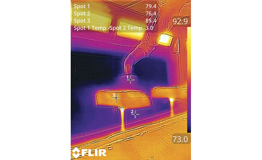
Still, old paradigms die hard and we encountered a great deal of resistance to the concept. Fortunately, during some of our subsequent work we were able to photograph a bell applying clearcoat with a thermal camera and, as they say, a picture is worth a thousand words (and calculations for that matter). Shown in Figure 1, the picture clearly shows that even the particles in the cloud that have travelled past the part are still within 3.0 °F of the temperature of the paint exiting the bell (Spot 1-Spot 2). This lends visual evidence to support the thermal model and proves, once again, that you just can’t argue with physics.
The Myth Dispelled
Simply dispelling the myth doesn’t answer the question, “Why do we continue to have temperature-based process fluctuations when we have a very tightly controlled ambient environment?” Ever since we introduced the concept of point-of-application temperature-based viscosity control in 1990, we have been searching for the answer to that question. It turns out that there is not just one single answer. To understand it, we must start by understanding the hierarchy of the various temperatures involved in the painting process.
The Temperature Hierarchy
There are three basic temperatures that must be managed in order to accurately control the painting process. They are (in order):
- The substrate,
- The paint,
- The air.
Substrate Temperature
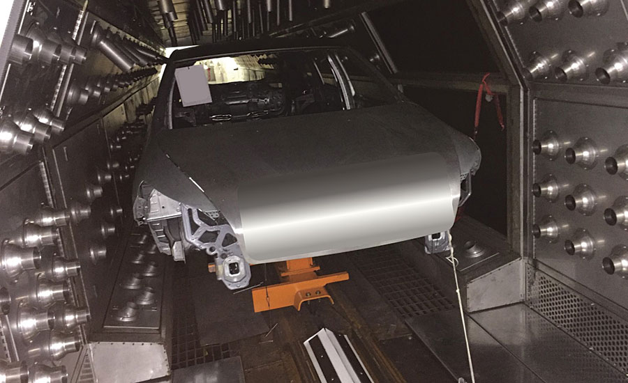
The impact of substrate temperature is often acknowledged and seldom addressed. This can be complicated because substrates vary. The part may be made from metal, plastic, composite, wood or any of thousands of other materials. But the real reason substrate is important in our thermal discussion is mass. The substrate will usually have a mass that is orders of magnitude greater than the mass of the paint film. This means that the paint will very quickly assume the temperature of the substrate once it hits the surface. We can see in Figure 1 that the part is warmer than the paint being applied. This means that, once the paint hits the surface of the part, the viscosity will drop until the warming solvents flash off to start the curing process. As a result, substrate temperature has a greater influence on the paint than does ambient temperature. Is it any wonder that many modern, progressive paint shops incorporate part temperature control into their process as shown in Figure 2?
Paint Temperature
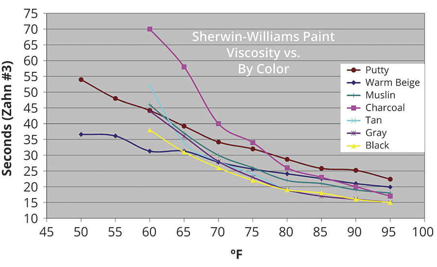
Paint temperature directly affects flash off, with warmer paint flashing off faster than colder paint. In addition, like most fluids, temperature inversely affects paint viscosity. As shown in Figure 3, as the temperature increases, the viscosity falls. Conversely, as the temperature falls, the viscosity increases. This temperature-based change in viscosity affects things like flow out, run and sag, orange peel, and gloss, just to name a few. With this kind of impact, paint temperature is certainly more important to controlling the process than ambient air temperature.
Air Temperature
We’ve already established that booth ambient temperature does not have as big an impact on the paint droplets as most people think. But that doesn’t mean that air can’t impact our process outcome. It turns out that air impacts many of the devices in our paint path – especially those metal devices that can easily transfer energy with the air – and therefore disrupt our process control strategies.
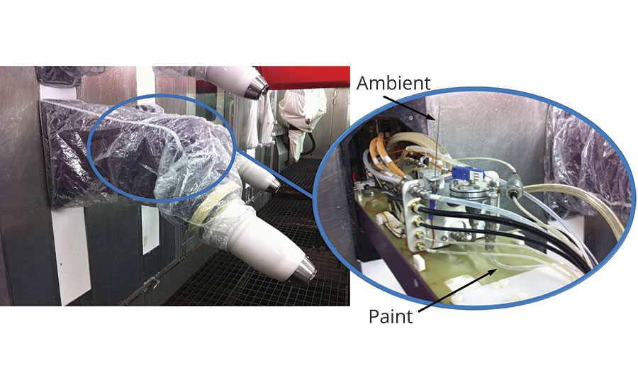
A really good example of this appeared when we measured the ambient and paint temperatures in an automotive bell applicator system in a process already equipped with paint temperature control in the recirculation loops. The measurement setup is shown in Figure 4. One would expect the temperature to be stable, yet when we examine measurements taken over a five-day period, as shown in Figure 5, the result was definitely anything but stable.
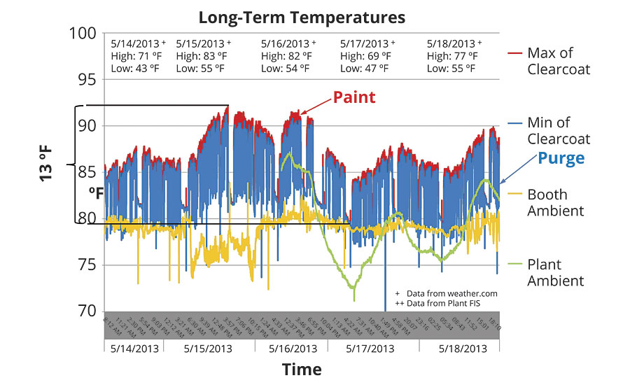
Here we see a full 13 °F of temperature variation. Furthermore, the booth ambient temperature was reasonably stable in the 75-80 °F range. While this long-term trend is important, more important is the impact of temperature variation on each individual paint cycle – which is the underlying reason for controlling temperature in the first place. Zooming in on this graph, as shown in Figure 6, we get a view of how temperature varies at the bell.
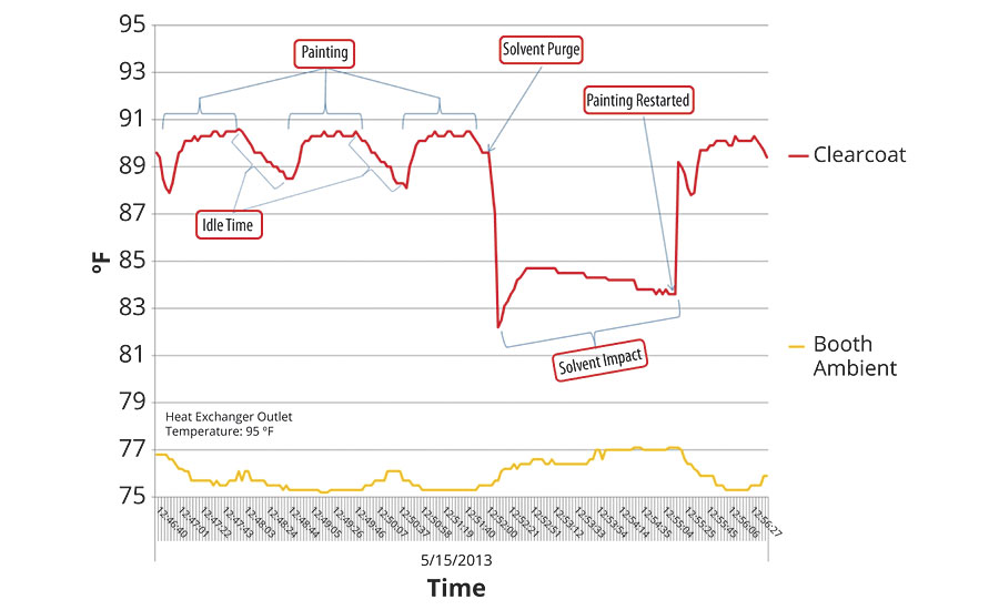
This tells a very different story. Here we can see that paint temperature is fairly stable during the painting cycle, though well off the 95 °F HX outlet temperature. The temperature falls during the idle time between each cycle and during solvent purge. Each one of these losses of temperature must be overcome during the next paint cycle, which means variation on each and every cycle. In examining this graph it is easy to jump to the conclusion that all of this is due to the average 76 °F ambient.
So, air temperature does have an impact on the paint process, but primarily due to its influence on piping and devices in the paint path between the heat exchanger outlet and the point of application. As shown in Figure 7, these devices include regulators, flow meters, color changers and a host of other devices.

Often, these devices are located at the booth wall, either inside or outside the booth. If outside, they may or may not be in a controlled environment. In most cases, placement is driven more by available space, or the desire to minimize paint waste, than for temperature concerns. A recent trend is to place these devices directly in the arm of the robot, as shown in Figure 8.

The goal of placing the color change and other components as close to the point of application as possible is sound, but as is often the case, there is more to the story.
When these devices are moved to the robot arm it increases the complexity. First, everything must be mounted and routed to accommodate the motion of the robot. In addition, the payload limitations of the robot must be taken into consideration. This often means that circulation at the color changer is eliminated, which reduces the number of paint lines by half, but can lead to issues with pigment separation (settling), excess purge requirements and cleaning issues, just to name a few. Moreover, these devices are expensive and must be protected, yet accessible for service when required. The most common method employed to prevent the contamination of the devices and the robot with paint overspray is a flexible cover of either fabric or plastic, as shown in Figure 9. These do double duty, not only protecting the robot and devices, but also preventing the leakage of air, oil, water, paint, solvent and the like from the robot into the paint environment, which could negatively impact finish quality.

The Hidden Air Problem
These covers create an artificial environment around the robot arm, but not necessarily at our carefully controlled booth environment. This contained environment can be affected by heat generated by the robot’s motors and bearings, and by fluids flowing through the tubing on the arm including the paint, solvent, etc. But there is one factor that is generally overlooked – cooling caused by the release of compressed air.
Compressed air is used to drive the bell turbine, and for shaping the particle cloud and directing it at the target part. The effects of this cooling phenomenon in pneumatic devices has long been studied and understood. It causes condensation and, in the worst cases, can even result in ice formation on exhaust mufflers. The ability of this ice to stop pump operation is well-documented. So why does this happen?
The Combined Gas Law
The refrigeration caused by decompressing air is explained by the Combined Gas Law, defined by the equation:
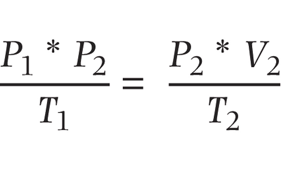
Where:
P = Pressure
V = Volume
T = Temperature
As the name implies, it is a combination of Boyle’s Law (1662), Charles’s Law (1787), Gay-Lussac’s Law (1809) and Avogadro’s Law (1811). Without getting too deeply into the mathematics, if the compressed air is being supplied at 80 PSI and we release it to atmosphere (at ~14.7 PSI), the temperature must fall to balance the equation. In addition, the expanding gas pulls energy from the surrounding surfaces, which makes them colder. These are the same principles employed to air-condition your home or chill the beer in your refrigerator. So, what does this have to do with the temperature of our paint?
Undercover Cooling
As this air is exhausted, it is trapped under the cover surrounding the robot. This lowers the temperature of the environment around the devices on the arm to well below the surrounding booth ambient temperature. In short, we’re creating a refrigerator around our robot arm. This is clearly demonstrated in Figure 10.

The green trace shows the clearcoat entering the booth, and the orange trace shows the clearcoat as it enters the bell. The blue trace is booth ambient. Around 7:15 a.m., we see the clearcoat entering the booth and increasing toward 80 °F. We see the clearcoat to the bell tracking the incoming temperature with an offset of about 2.5 °F. We would normally attribute this to the influence of booth ambient on the coating as it travels along the arm of the robot to the point of application.
But a funny thing happens when painting is stopped for the break at about 7:20 a.m. As we would expect, with the paint sitting stationary, the clearcoat at the booth wall loses temperature, nearly reaching booth ambient by the end of the break. The clearcoat at the bell inlet however, continues to lose temperature, falling a full 2 °F below booth ambient by the end of the break. Since this “sub-cooling” clearly cannot be the result of the booth ambient air, it must be originating from another source – a colder source – and that source can be found in the exhaust air shown on the graph as the brown trace. We can see that this air hovers between 60-65 °F, barely exceeding 65 °F during the breaks when consumption is at its minimum.
It is easy to see how this can be misinterpreted as booth ambient influence. When the lines are purged to restart painting at about 7:50 a.m., the clearcoat inlet and bell temperatures come together and then the bell temperature sits between the clearcoat inlet and booth ambient temperature over the next two hours of runtime. But when we consider that the clearcoat is flowing through Teflon tubing which, being plastic, provides some level of insulation, and also factor in the dwell time in that tubing during continuous paint cycles, it is clear that the temperature differential between the clearcoat inlet temperature and the booth ambient temperature is insufficient to produce this drop in temperature.
From a process control and finish quality repeatability perspective, the influence of this refrigerated air is not consistent. As shown in Figure 10, it varies based on the time between racks (varying gaps), based on breaks, downtime, shutdowns, etc. It varies based on the rate of change, which is determined by the temperature differential between the coating temperature and the refrigerated air temperature. And the refrigerated air temperature varies based on the pressure and flow rate, which can vary based on different parts being coated. These variations are made evident when we look at the lunch break starting about 9:55 a.m. and continuing through the 10:30 a.m. hour.
Unfortunately, these variations are virtually invisible to the line operators and process engineers, which can make it very hard to identify them as the source of finish quality issues. This is especially true in this example, where the booth ambient temperature (probably the only temperature being measured) moves nearly 8 °F in just three hours.
Solving the Problem
From this it is clear that controlling exhaust and shaping air are likely more important than booth air in gaining tight control over the painting process. The solution, however, is nearly as complex as identifying the problem in the first place. It requires monitoring the exhaust air temperature and then controlling the incoming compressed air temperature with a closed-loop system designed to assure that the exhaust air temperature matches the paint temperature setpoint, independent of changes in plant ambient, booth ambient and compressed air temperature. This requires a sophisticated temperature control system with strategically placed sensors and an advanced control algorithm.
One side benefit of this system is that it will also stabilize the shaping air temperature, maintaining it at a point where it is unlikely to generate condensation and therefore the “spitters” often associated with this refrigeration and often addressed by other hot gas systems that overheat the air (or other gases) and thus creating dry spray.
Adding this to a modern paint temperature control solution can significantly improve finish quality, resulting in higher first-pass yields and more predictable process outcomes independent from variations in ambient temperature that occur from day-to-night and from season-to-season. This can also significantly reduce operating cost, increase throughput and therefore enhance your competitive position in the marketplace.
What to Read Next:
Paint Temperature Control Solves Finishing Defects
Dissecting Orange Peel - A Process-Oriented Approach, Part 1
Dissecting Orange Peel - A Process-Oriented Approach, Part 1
Looking for a reprint of this article?
From high-res PDFs to custom plaques, order your copy today!


