Nanostructured, Nonuniform and Core-Shell Polyurethane Dispersions

Nonuniform Emulsion Polymers
Core-shell emulsion polymer particles are well known in the art; they are produced primarily with radically polymerizable unsaturated monomers such as acrylates and vinyls. Staged or sequential emulsion polymerization processes are generally used.1 First, a monomer or a mixture of monomers is polymerized by a conventional emulsion polymerization technique forming first-stage particles. Then a second mixture of polymerizable monomers and a polymerization initiator are added to the first-stage emulsion to effect polymerization. In the second stage, if monomers and conditions are selected correctly, a coating ("shell") around the first-stage particle ("core") may be formed. If desired, multiple shells can be formed over the same particle through sequential polymerization. This process is made possible by a simple fact - the monomers used in emulsion polymerization diffuse from pre-emulsified droplets into the polymer particles that are the major loci for polymerization (Figure 1).A similar approach is used to make polyurethane-acrylic hybrids as described in U.S. Patent Nos. 4,644,0303 and 5,137,961.4 In essence, instead of one of the acrylic stages, a polyurethane is used.
PU oligomers, however, do not diffuse through the aqueous phase. Therefore the route of sequential addition is not suited for making composite PUDs. Is it possible to overcome this fundamental obstacle?
Prior Art
While much prior art deals with various methods of producing aqueous polyurethane resins and polyurethane dispersions, no publications appear to disclose an effective method of preparing water-dispersible non-uniform and nanostructured, in particular core-shell, polyurethanes.There have been several attempts in patent literature to make core-shell PUDs.5-8 According to one patent,5 one isocyanate-terminated polyurethane prepolymer (A) is dispersed into an aqueous dispersion of polyurethane (B). It is stated that various morphologies, including core-shell, can be obtained. According to this process, however, one component (B) is already made into a stable dispersion. In this situation, particles are colloidally stable due to the double electric layer and/or steric hindrance, which prevent their flocculation, and the particles have inherent resistance to coalescence with other particles. Water creates a barrier between the prepolymer A and dispersion particles B. Therefore, the final product is a rather heterogeneous mixture of three types of particles: (1) pure particles A, (2) pure particles B, and (3) hybrid particles A+B (if any).
According to another patent,6 two different prepolymers, in separate streams, are dispersed in water simultaneously. Purportedly core-shell particles are formed due to the different hydrophilicities of the two prepolymers. In fact, the aforementioned arguments apply to this approach also, and true core-shell morphology cannot be obtained by the disclosed process. When we tried to reproduce the described procedure, no evidence of core-shell formation was found. In addition, when an attempt was made to make one of the prepolymers more hydrophobic by reducing its acid content, a very unstable dispersion with substantial settling was formed. Both methods described in patent references 5 and 6 fail completely if one of the prepolymers does not contain a dispersing monomer.
In this paper, we propose a new process that overcomes the above-mentioned reliance on the agglomeration of two types of particles to produce hybrid particles.

PUD Prepolymer Process
Let us first consider briefly a typical method for making waterborne polyurethanes known as the "isocyanate prepolymer process".9 It is comprised of two stages and usually utilizes two vessels: a prepolymer tank and a dispersion tank. During the first stage, a polyol, a stoichiometric excess of diisocyanate and a dispersing monomer, for example dimethylol propanoic acid (DMPA), are reacted in the prepolymer tank, forming a prepolymer (Figure 2).Polyols are relatively low-molecular-weight oligomers (Mn ~ 500 to 3,000 g/mol) bearing primary (for high reactivity with -NCO group of diisocynates) hydroxyl groups on both ends. The two widely used types of polyols are polyesters (e.g., poly(1,6-hexamethylene neopentyl adipate), HNA) and polyethers (e.g., polypropylene glycol, PPG). Polycarbonates, despite their superior properties, are used less often due to their significantly higher cost. Other less-common polyols include polyacetals, polycaprolactones, acrylate polyols, silicone polyols and halogenated polyols.
The selection of diisocyanates is not as diverse as that of polyols. The most widely used diisocyanates are shown in Figure 3. They are divided into three groups: aromatic (TDI, MDI), aliphatic (hydrogenated MDI, IPDI) and araliphatic (TMXDI) isocyanates.
Dimethylol propanoic acid is the most commonly used dispersing monomer. Other specialty dispersing monomers are also available. At the end of the prepolymer step, reacted DMPA is neutralized with tertiary amine, often triethylamine. Primary and secondary amines cannot be employed for neutralization because they are extremely reactive with the isocyanate groups still present at this stage. Neutralization of the carboxylic group of the DMPA segment forms a very hydrophilic salt.
During the second step of the prepolymer process, prepolymer, a viscous liquid, is transferred from the prepolymer tank into an agitated dispersion tank containing water. The hydrophilic neutralized DMPA segments favor the water phase but, because they are anchored to the polymer backbone, are restrained at the polymer/water interface. The initial surface of prepolymer in water is not large enough to accommodate all DMPA units. This creates the thermodynamic drive to increase surface area. As a result, with the help of agitation, original large particles of prepolymer are broken into progressively smaller particles until the demand for the polymer/water interface is satisfied (Figure 4).
Once a stable dispersion of small particles is formed, the prepolymer, which still has a low molecular weight, is extended with diamines such as ethylene diamine or hydrazine. The amount of extender is carefully selected based on the available unreacted NCO and is targeted very close to stoichiometry in order to achieve maximum molecular weight. Thus, a fully reacted high-molecular-weight polyurethane dispersion is formed.

Nanostructured PUD Process
We speculated that the prepolymer process described above can be adopted to make non-uniform PU dispersions in the following way. Similar to U.S. Patent No. 5,959,003, two prepolymers with different hydrophilicities are prepared separately. But this is where the similarity ends. The key distinguishing feature of our process is that the two prepolymers are intimately pre-mixed before the dispersion step (Figure 5). After dispersing the prepolymer mixture in water, hybrid particles containing both prepolymers are formed. Because the two components are now in the same particle, they do not have to diffuse through the water phase or co-flocculate as discussed above. The mixture "remembers" that it was made of the two different prepolymers and, in the presence of water, diffusion of hydrophilic components to the water-particle interface and of hydrophobic components to the interior of the particle begins. If the diffusion and phase separation are complete, perfect core-shell morphology is formed.
Thus, we had a convincing theory; however, according to Murphy's Laws on Technology10, "Logic is a systematic method of coming to the wrong conclusion with confidence." So we had to experiment.
First Successful Core-Shell PUD
There are a number of ways to differentiate the hydrophilicity of prepolymers. One obvious route is to change the amount of dispersing agent, whether it is anionic (DMPA), cationic (e.g., N-methyl diethanol amine), amphoteric or nonionic (monomers with side-chain poly(ethylene oxide)).In order to prove the concept, two different prepolymers were prepared. One prepolymer contained DMPA, while the other one did not. After the prepolymers were prepared in separate reactors, they were mixed together in one reactor, neutralized, dispersed and extended.
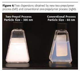
Parallel to the above experiment, a control experiment was also conducted. A single prepolymer was made from the same ingredients. It was neutralized, dispersed and extended the same way as in the first experiment. The products obtained in these two parallel reactions are shown in Figure 6.
The significant difference in appearance of the two dispersions made from identical components indicated that two different compositions of matter were prepared. For unequivocal proof, we turned to electron microscopy.
Transmission Electron Microscopy (TEM)
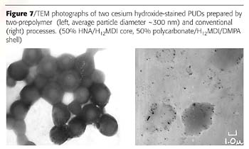
TEM is similar to optical microscopy but, instead of visible light, a beam of electrons is used. When the beam passes through a sample, denser areas allow fewer electrons to penetrate through, resulting in darker appearance in the processed image. Less-dense areas are more transparent to the electron beam, and thus appear lighter.Unfortunately, common polyurethane components have just about the same densities, so good contrast images are difficult to obtain. Several staining techniques are available to enhance contrast.11 They are based on the preferential reaction or association of the stain with certain polymer components. Cesium hydroxide, which reacts with acid groups, was found to produce adequate contrast. The atomic weight of cesium is ~130 a.u. It serves as a good barrier to the electron beam. The cesium cations are attracted to the carboxylic anions of DMPA segments and concentrate in the areas with high contents of these segments.
A TEM image obtained with the Philips CM12 Transmission Electron Microscope on the core-shell sample stained with CsOH is shown in Figure 7 (left). For comparison, a photograph of the control sample made from a single prepolymer, which contained all the same components mixed in one reactor, is shown on the right.
These pictures provided direct proof that a true core-shell PUD was made. To our knowledge, this is the first direct evidence of its existence.
The DMPA segments can migrate to the water interface regardless of which process is used to prepare the PUD. In order to study the fate of other prepolymer components, other staining techniques are needed.
Bromine Staining
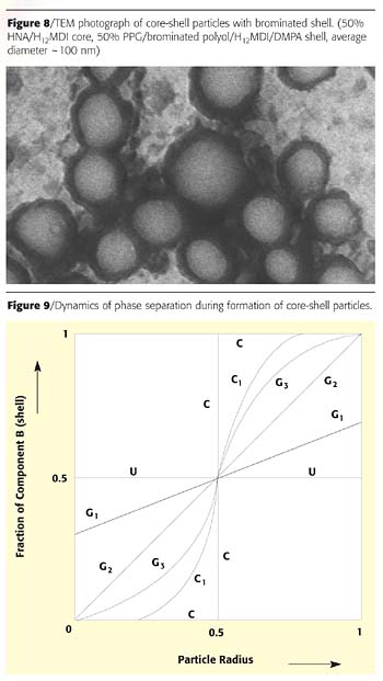
One easy way to introduce a heavy element into the backbone of polyurethane is to use brominated polyols. This approach also gave us clear core-shell images (Figure 8). The only drawback to using the bromine staining technique is that high-energy electron beam ablates the bromine-containing phase rather quickly, and the image needs to be recorded immediately upon irradiation.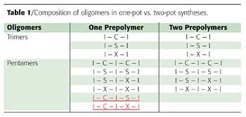
Analysis of Oligomers Formed at Prepolymer Stage
In order to understand the origin of the unusual "memory" of the prepolymer mixture and why the two-prepolymer process works, let us consider in detail what happens during prepolymer formation on the molecular level.In the simplest case, the reagents used are:
-
I - diisocyanate
X - hydrophilic monomer such as dimethylol propanoic acid
C - core polyol
S - shell polyol
For comparison, a traditional process is used in a separate experiment where all four components I, X, C and S are mixed and reacted in one reactor.
In the prepolymer stage, isocyanate monomers are commonly used in stoichiometric excess to have terminal NCO groups for further extension with diamine. The usual equivalent ratio of ~NCO to ~OH is ~1.5-2 to 1, which is needed to control the prepolymer viscosity. Trimers predominantly form in this step (see also Table 1):
Core prepolymer: Shell prepolymer:
I - C - I I - S - I, I - X - I
Thus, the mixture of the two prepolymers is comprised of the following trimers:
I - C - I, I - S - I, I - X - I
But, in the control one-pot experiment, where the same four starting monomers react together in one reactor, the identical trimer mixture forms:
I - C - I, I - S - I, I - X - I
Fortunately, in step-growth polymerization (a.k.a. polycondensation), there is always a distribution of oligomer chain lengths, and even at the 2:1 NCO to OH ratio, some longer oligomers (pentamers, heptamers, etc.) form. As we show below, it is these longer oligomers that make all the difference.
Let us expand the oligomer analysis to pentamers (Table 1). Note that in the control one-pot experiment, two distinct pentamers form:
I - C - I - S - I, I - C - I - X - I
We hypothesize that these two species function as compatibilizing agents preventing the establishment of counter diffusion of hydrophilic and hydrophobic components in the control experiment.
The two-pot synthesis selectively eliminates these compatibilizers. When the mixture of the two prepolymers is exposed to water, the hydrophilic pentamers I- S - I - X - I and I - X - I - X - I begin their diffusion to the particle-water interface. Because "like likes like", the pentamer I - S - I - X - I "drags" the pentamer I - S - I - S - I and the trimer I - S - I to the surface, leaving the pentamer I - C - I - C - I and the trimer I - C - I behind in the particle interior.
In contrast to the two-prepolymer experiment, in the one-pot synthesis the pentamer I - C - I - C - I has its own hydrophilic counterpart in the form of I - C - I - X - I, and the shell components have no advantage over the core in the diffusion to the particle surface. In addition, the hetero-pentamer I - C - I - S - I is a good compatibilizer for the homo-pentamers I - C - I - C - I and I - S - I - S - I and the I - C - I and I - S - I trimers, which prevent their separation. Similar analysis can be easily applied to the mixture of heptamers and higher oligomers.
Theoretical Considerations
Diffusion vs. Phase Separation
There are two key competing processes occurring simultaneously during morphology development (during the dispersion of the prepolymer and the mixing of the dispersion but before the extension):1. The diffusion of hydrophilic components to the water-particle interface and migration of hydrophobic components into the middle of the particle,
2. The phase separation of the two (or more) components due to their thermodynamic incompatibility.
The dynamics of diffusion and phase separation during the core-shell formation is shown in Figure 9 using an example of a mixture of component A (hydrophobic core) and B (hydrophilic shell).
It starts with a uniform mixture of oligomers coming out of the prepolymer reactor (trace U). When the prepolymer mixture is dispersed into water, the counter-diffusion of hydrophilic and hydrophobic components begins, and the system goes through a continuum of gradient morphologies (G1 k G2 k G3). At a certain point, a distinct core and/or shell is formed with a transitional interlayer (trace C1). Ultimately, the transitional interlayer shrinks and disappears, and a perfect core-shell particle is formed with distinct phase separation between the core and the shell (trace C).
One can easily imagine some mixed cases, such as the combination of linear and non-linear gradients, along with phase separation. The plot of fraction B versus distance from the particle center does not have to (and most likely will not) pass through the (0.5, 0.5) coordinate. Figure 9 shows only a simplified case.
Any of the intermediate morphologies can be "frozen" by chain extending the dispersion when the desired morphology is reached. Chain extension results in abrupt molecular weight increase which, in turn, leads to a jump in polymer intrinsic viscosity within the particle. Diffusion slows down dramatically and the morphology becomes fixed.
Diffusion
The relative rates and duration of diffusion and phase separation will determine, to a large extent, the morphology of the particles. The following factors will impact the diffusion rates: molecular weights and molecular weight distributions; temperature; viscosity; low-molecular-weight diluents (solvents, plasticizers, reactive monomers, etc.); specific interactions between components (hydrogen bonding, dipole-dipole interaction, complexation, etc.); electron donors and ionic additives, which interfere with the hydrogen bonding; branching; grafting of the two phases; spontaneous chain extension by water, which increases prepolymer molecular weight.Phase Separation
The following factors are expected to promote phase separation: difference in chemical nature of the polyols and isocyanates used; difference in polarity and/or hydophilicity/hydrophobicity of the two phases; selective plasticization by water; increased molecular weights; chain extension; selective or preferential neutralization; crystallinity; solvent extraction into water phase.On the other hand, the following will inhibit phase separation: low-molecular-weight diluents, which are good solvents for both components; incomplete reaction during the formation of prepolymers; specific interaction; and complex formation between the two prepolymers.
As one can see, several factors play various roles in both diffusion and phase separation, complicating the picture and hindering the ability to predict the particle morphology that will result. Consequently, experimentation may be required to determine which reactants or reaction conditions should be used in order to obtain the desired morphology.
Surface Tension as a Driving Force
One also has to consider the interfacial surface tension between the three phases: water and prepolymer A, water and prepolymer B, prepolymer A and prepolymer B.12 The system will move in the direction of minimizing its total energy, which is comprised of three components:Etotal = SAW*sAW + SBW*sBW + SAB*sAB
where
Etotal - total system energy
sAW - surface tension between water and phase A
sBW - surface tension between water and phase B
sAB - surface tension between phase A and phase B
SAW - surface area between water and phase A
SBW - surface area between water and phase B
SAB - surface area between phase A and phase B
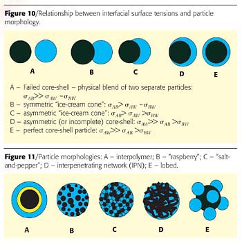
Figure 10 shows some of the morphologies that are likely to be formed as a result of a particular interrelationship between the surface tensions. In general, the surface with the highest interfacial surface tension will tend to disappear and surface area with the lowest surface tension will grow larger so that the sum Etotal will decrease.
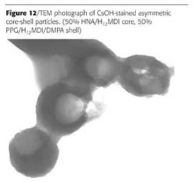
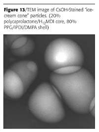
Some other morphologies known for emulsion polymers are shown in Figure 11. It was found that the two-prepolymer method is quite versatile and is capable of producing at least some of these particle morphologies. The two examples are shown in Figures 12 and 13.
Guidelines for Preparation of Nanostructured PUDs
Although it is difficult to predict which particular morphology will result from a specific experiment, some general guidelines can be offered to direct experimentation toward the desired result.
Generally, it is preferable to have compatible (miscible) prepolymers to ensure their intimate mixture and, as a result, a uniform dispersion comprised of particles with essentially the same morphology. The preferred driving force for morphology development, especially core-shell, is difference in hydrophilicity. This, however, is not the only route to achieve phase separation. Immiscibility of the two (or more) prepolymers can be induced at the dispersion step and/or during extension and/or thereafter by a number of factors which are considered above in detail.
Cryogenic Scanning Electron Microscopy (CryoSEM)
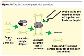
In conclusion, we present results obtained through the use of Cryogenic Scanning Electron Microscopy, which proved useful in the analysis of larger particles (>1µm). This technique utilizes a special sample preparation, which is shown in Figure 14.A very small aliquot of PUD is placed as a droplet on a tiny cryoSEM carrier (hollow rivet). Another identical carrier is placed atop the droplet in an inverted position and is held in place by surface tension. The entire assembly is frozen first in liquid nitrogen and then in a solid/liquid nitrogen slush. Then the top carrier is knocked off using the remote fracture probe. If the procedure is successful, the droplet fractures through its interior. The water is removed from the sample by vacuum sublimation at -95 ºC. This is known as the "etch" step. Once the structures are revealed, the sample is sputter coated with a very thin layer of gold at below -130 ºC to render it conductive. After metallizing, the sample is examined by SEM.
Similarly to TEM, SEM employs an electron beam to study small objects. A high-energy-focused electron beam scans across the coated surface of a sample and knocks out secondary electrons, which are registered. Thus, a high-resolution 3D image is created.
We used the scanning electron microscope (SEM) and cryogenic system at Ohio Wesleyan University. The SEM is a LEO (now Carl Zeiss SMT) 435 VP and the cryo system is an Oxford (now Gatan) CT1500.
Rubbery Core - Glassy Shell
("Modulus Staining")
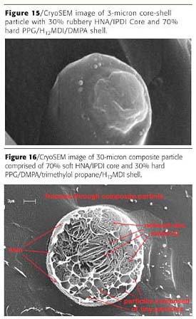
Core-shell particles are well-known toughening agents for plastics.13 Figure 15 shows a cryoSEM image of the particle, which has a rubbery core and a glassy shell.Interestingly, the hard shell fractured like glass, giving a smooth surface. Conversely, the rubbery core, rather than fracturing straight through, was ripped apart like a piece of rubber. In a sense, this is a visual record of the toughening mechanism of core-shell particles.
The particle size can have a significant impact on the final morphology. In smaller particles, the diffusion path for hydrophilic components to the surface of the particle and for the hydrophobic components to the center of the particle is shorter. Therefore, core-shell morphologies are favored when the particle size is smaller.
For larger particles, more complex morphologies are expected, with possibly several morphologies co-existing within the same particle. This is illustrated on Figure 16. The image of this 30-micron large particle is a snap shot of the dispersion process frozen in time. It reveals several distinct morphological features, which need further exploration and the nature of which is open for discussion.
Conclusions
A new methodology for making nanostructured and nonuniform polyurethane dispersions having a wide variety of morphologies has been developed. The method is comprised of the preparation of two prepolymers with different hydrophilicities. The key distinguishing feature of the process is that the two prepolymers are intimately pre-mixed before the dispersion step. Surprisingly, the mixture "remembers" that it was made of the two different prepolymers and, in the presence of water, diffusion of hydrophilic components to the water/particle interface and of hydrophobic components to the interior of the particle begins. The origin of this unexpected memory is shown to reside in pentamer and higher oligomer compositions. The interplay of diffusion, phase separation and chain extension determines the morphological outcome. Various previously inaccessible PU particle morphologies, including core-shell and "ice-cream cone", have been prepared. This novel patent-pending technology opens up new horizons for PUD chemistry.Acknowledgements
The authors would like to thank Noveon, Inc., for the permission to publish this paper. We are grateful to Professor Laura Tuhela-Reuning for her assistance with CryoSEM work, which was performed at the Department of Botany and Microbiology, Ohio Wesleyan University. We also would like to thank Elizabeth Lubnina for editing the paper.References
1 Lubnin, A.V.; Stanislawczyk, U.S. Patent 6,479,147, 2002.2 Poehlein, G.W. Encyclopedia of Polymer Science and Engineering, 2nd Edn., Mark, H. F., et al., Eds, Vol. 6, p. 1, 1986.
3 Loewrigkeit, P.; Van Dyk, K.A. U.S. Patent 4,644,030, 1987.
4 Goos, H.C.; Overbeek, G.C. U.S. Patent 5,137,961, 1992.
5 Duan, Y.; Wei, Y.; Zhu,Y.; Stammler, S.E.; Marty, B.L.; Haider, G.J.; Davies, R.R.; Maksymkiw, M.J. U.S. Patent 6,017,998, 2000.
6 Lo, H.; Jan, Y.; Wen, H.; Chen, W.; Chang, N. U.S. Patent 5,959,003, 1999.
7 Knauss. D.M. U.S. Patent 6,252,014, 2001.
8 Knauss, D.M.; Clark, S.L. Polymer Preprints, 43(1), 324, 2002.
9 Dieterich, D. Progress in Organic Coatings, 9, 281, 1981.
10 http://www.murphys-laws.com/murphy/murphy-technology.html
11 Sperling, L.H. Encyclopedia of Polymer Science and Engineering, 2nd Edn., Mark, H.F. et al., Eds, Vol. 9, p. 760, 1986.
12 Torza, S.; Mason, S.G. J. Colloid & Interface Sci., 33, No.1, 67, 1970.
13 Sue, H.J.; Garcia-Meitin, E.I.; Pickelman, D.M.; Yang, P.C. Toughened Plastics I,Riew, C.K.; Kinloch, A.J. Eds, p. 259, 1993.
This paper was presented at the International Waterborne, High-Solids and Powder Coatings Symposium sponsored by The University of Southern Mississippi, Department of Polymer Science, February, 2005 New Orleans.
Looking for a reprint of this article?
From high-res PDFs to custom plaques, order your copy today!


