Selecting the Right Pollution Control System
Modern emission control equipment offers multiple choices in technologies, temperatures, operating costs and energy efficiency. Choosing the right system requires an understanding of the different technologies, as well as the specific needs of the application.
Since the early 1970s, many finishing operations have had to install emission control systems to destroy volatile organic compounds (VOCs) and/or hazardous air pollutants (HAPs) - or be faced with the possibility of stiff non-compliance fines. While general guidelines regarding the destruction of air pollutants present in process exhaust air streams are somewhat consistent within the overall industry, a company’s individual requirements and desires can vary greatly.
Developing an optimal design for each operation depends on many variables, including the type and quantity of air pollutant, the volume and temperature of the air being exhausted, and other factors. Future manufacturing growth expectations and even the facility’s geographical location should also be considered. By understanding the modern, efficient designs now available and by taking into consideration the various selection criteria, companies can be better prepared to specify and select a custom designed air pollution control system (APCS) that will meet their needs both now and in the future.
Thermal Oxidizers
Designed to operate at temperatures of 1,400 to 1,500°F (760 to 815°C), thermal recuperative oxidizers use a tube-in-shell stainless steel heat exchanger as an air preheater (see Figure 1). Oxidation is achieved as the process exhaust is passed through the heat exchanger, mixed, and held at elevated temperatures in the combustion chamber for a minimum of 0.5 second. Older thermal oxidizers achieved from 40% to 60% thermal efficiency and up to 95% destruction efficiency. Modern thermal oxidizers are designed for up to 80% thermal efficiency and up to 99% destruction efficiency.
 Regenerative Thermal Oxidizers
To achieve destruction in a regenerative thermal oxidizer (RTO), the air pollutant collected from the manufacturing process is directed by the APCS supply fan into the RTO inlet manifold and through one of the two energy recovery canisters by use of inlet control (switching) valves (see Figure 2). The air pollutant passes from the valve assembly vertically upward through the first of the two heat exchanger canisters, where it adsorbs heat from the ceramic media, thus cooling the media and preheating the air stream. The preheated air then enters the combustion chamber, typically at a temperature very close to the temperature required for thermal oxidation. In the combustion chamber, the air is heated further to 1,500°F (if necessary) and held at this oxidation temperature for a period of time (typically 0.5 second or more) sufficient to achieve a high destruction efficiency. Destruction of the air pollutant takes place within the combustion chamber, where auxiliary fuel is introduced if necessary.
The clean, hot air then passes from the combustion chamber vertically downward through the second energy recovery canister. Heat generated during thermal oxidation of the air pollutant is then adsorbed by the ceramic media, thus cooling the air and preheating the media. Finally, the clean, cooled air is routed to atmosphere through an outlet control (switching) valve, exhaust manifold and the APCS exhaust stack. To maximize the heat exchange, the valves can be switched to alternate the airflow path between the canisters every three to five minutes, which continuously regenerates the heat stored within the ceramic media.
Older RTOs achieved from 80 to 90% thermal efficiency and up to 95% destruction efficiency. Modern RTOs are designed for up to 97% thermal efficiency and up to 99% destruction efficiency.
 Catalytic Oxidizers
Catalytic oxidizers are designed to use an industrial grade catalyst to promote a chemical reaction (oxidation) at lower temperatures compared to thermal oxidation, typically between 500 and 650°F (260 and 343°C) (see Figure 3). Because of the lower operating temperatures, catalytic oxidation commonly requires less energy to operate. To minimize operating costs, catalytic oxidizers incorporate a high-efficiency, counter-flow plate type heat exchanger to preheat incoming exhaust fumes from the production process. Oxidation is achieved when the fumes are passed through a bed of industrial grade catalyst manufactured of pure platinum group metals.
Older catalytic oxidizers achieved only 50 to 70% thermal efficiency and up to 95% destruction efficiency. Modern recuperative catalytic oxidizers are designed for up to 80% thermal efficiency and up to 99% destruction efficiency.
 Rotary Concentrator Systems
A rotary concentrator system is a hybrid APCS designed to remove and destroy air pollutants from a process exhaust air stream efficiently (see Figure 4). Application of this technology is limited to exhaust air steams at or near ambient temperature. The system requires a two-step process:
The rotor is fabricated from a corrugated mineral fiber substrate to which the manufacturer permanently bonds a proprietary mixture of hydrophobic zeolite and inorganic materials. The hydrophobic zeolite rotor is inorganic and inert, and it has rigidity, physical integrity and the ability to withstand thermal stress. In this application the zeolite removes the air pollutant from the manufacturing process exhaust air stream as it passes through the rotor.
The concentrator wheel rotates at an approximate speed of two to eight revolutions per hour, continuously passing a sector of the wheel with adsorbed air pollutant through a desorbtion plenum for removal by a heated air stream. The system thus continuously returns a regenerated (or clean) sector back into the main housing for further adsorbtion. For desorbtion, the slipstream of air that was routed through the cooling plenum is sent automatically through a supplemental desorbtion heater, were it is elevated to desorbtion temperature (typically ~350°F/176°C) and returned to the concentrator housing. This heated desorbtion air is directed back through the wheel by means of the desorbtion plenum, where the concentrated pollutants are removed. The highly concentrated air stream is then routed to the RTO for thermal destruction.
Secondary recovery units capture the 250 to 1,500 degrees of heat energy (depending on the APCS currently in use) that would normally be vented out of the stack to the atmosphere. The unit can be designed for minimal pressure drop so that it doesn’t affect the operation of the oxidizer while returning temperature controlled fresh air for a variety of uses. This heated fresh air can be used for building comfort heating, process make-up air (ovens/dryers, kilns, curing zones, etc), or in some cases, can completely replace the need for natural gas fired burners in the manufacturing process itself.
Using the same idea of capturing heat from the exhaust stream, a hot water or thermal oil heat transfer coil can be installed in the APCS exhaust stack. Hot water can be used for building comfort heating or can be returned to the process for use in air preheating, condensation control or another application. This coil could also be used as a preheat section to preheat cool water for a steam generator. Thermal oil is used as a main process heat source where direct flame heating is not desired. Adding a coil in the exhaust stream can reduce or even remove the heat load required from the thermal oil heating system. Depending on the stack temperature, the exhaust from the oxidizer could be routed directly to a low-pressure steam generator. If the plant uses steam for any reason (carbon bed regeneration, humidity control, etc.), this system could supplement steam production capacity any time the oxidizer is running. In an ideal situation, the steam produced from the oxidizer exhaust would allow the main steam generator to function as a backup system.
With today’s modern equipment incorporating components such as high efficiency heat exchangers, natural gas fired burners, industrial grade blowers, electric or pneumatic actuators and programmable logic controllers, the installation of a new system or replacement of an older system can offer a short-term payback on a company’s capital investment. Retrofitting a secondary recovery unit to an older air pollution control system can also generate significant energy savings. Either an upgrade or a retrofit could provide substantial operating savings and have a positive impact on a company’s bottom line.
For more information on air pollution control equipment, visit The CMM Group's website.
Modern, energy-efficient RTOs can significantly reduce natural gas costs while providing VOC/HAP destruction efficiency of up to 99%.
Since the early 1970s, many finishing operations have had to install emission control systems to destroy volatile organic compounds (VOCs) and/or hazardous air pollutants (HAPs) - or be faced with the possibility of stiff non-compliance fines. While general guidelines regarding the destruction of air pollutants present in process exhaust air streams are somewhat consistent within the overall industry, a company’s individual requirements and desires can vary greatly.
Developing an optimal design for each operation depends on many variables, including the type and quantity of air pollutant, the volume and temperature of the air being exhausted, and other factors. Future manufacturing growth expectations and even the facility’s geographical location should also be considered. By understanding the modern, efficient designs now available and by taking into consideration the various selection criteria, companies can be better prepared to specify and select a custom designed air pollution control system (APCS) that will meet their needs both now and in the future.
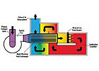
Figure 1. Airflow diagram of a thermal recuperative oxidizer.
Pollutant Destruction Technologies
The basic design concept of both thermal and catalytic oxidizers is to promote a chemical reaction of the air pollutant with oxygen at elevated temperatures. This reaction destroys the pollutant in the air stream by converting it to carbon dioxide, water and heat. The rate of reaction is controlled by three interdependent and critical factors: time, temperature and turbulence. What distinguishes one technology from another is the temperature at which the air pollutant is destroyed and the methods used to generate the heat used in the process.Thermal Oxidizers
Designed to operate at temperatures of 1,400 to 1,500°F (760 to 815°C), thermal recuperative oxidizers use a tube-in-shell stainless steel heat exchanger as an air preheater (see Figure 1). Oxidation is achieved as the process exhaust is passed through the heat exchanger, mixed, and held at elevated temperatures in the combustion chamber for a minimum of 0.5 second. Older thermal oxidizers achieved from 40% to 60% thermal efficiency and up to 95% destruction efficiency. Modern thermal oxidizers are designed for up to 80% thermal efficiency and up to 99% destruction efficiency.
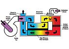
Figure 2. Airflow diagram of a regenerative thermal oxidizer.
To achieve destruction in a regenerative thermal oxidizer (RTO), the air pollutant collected from the manufacturing process is directed by the APCS supply fan into the RTO inlet manifold and through one of the two energy recovery canisters by use of inlet control (switching) valves (see Figure 2). The air pollutant passes from the valve assembly vertically upward through the first of the two heat exchanger canisters, where it adsorbs heat from the ceramic media, thus cooling the media and preheating the air stream. The preheated air then enters the combustion chamber, typically at a temperature very close to the temperature required for thermal oxidation. In the combustion chamber, the air is heated further to 1,500°F (if necessary) and held at this oxidation temperature for a period of time (typically 0.5 second or more) sufficient to achieve a high destruction efficiency. Destruction of the air pollutant takes place within the combustion chamber, where auxiliary fuel is introduced if necessary.
The clean, hot air then passes from the combustion chamber vertically downward through the second energy recovery canister. Heat generated during thermal oxidation of the air pollutant is then adsorbed by the ceramic media, thus cooling the air and preheating the media. Finally, the clean, cooled air is routed to atmosphere through an outlet control (switching) valve, exhaust manifold and the APCS exhaust stack. To maximize the heat exchange, the valves can be switched to alternate the airflow path between the canisters every three to five minutes, which continuously regenerates the heat stored within the ceramic media.
Older RTOs achieved from 80 to 90% thermal efficiency and up to 95% destruction efficiency. Modern RTOs are designed for up to 97% thermal efficiency and up to 99% destruction efficiency.
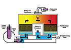
Figure 3. Airflow diagram of a catalytic oxidizer.
Catalytic oxidizers are designed to use an industrial grade catalyst to promote a chemical reaction (oxidation) at lower temperatures compared to thermal oxidation, typically between 500 and 650°F (260 and 343°C) (see Figure 3). Because of the lower operating temperatures, catalytic oxidation commonly requires less energy to operate. To minimize operating costs, catalytic oxidizers incorporate a high-efficiency, counter-flow plate type heat exchanger to preheat incoming exhaust fumes from the production process. Oxidation is achieved when the fumes are passed through a bed of industrial grade catalyst manufactured of pure platinum group metals.
Older catalytic oxidizers achieved only 50 to 70% thermal efficiency and up to 95% destruction efficiency. Modern recuperative catalytic oxidizers are designed for up to 80% thermal efficiency and up to 99% destruction efficiency.
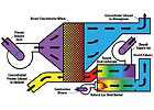
Figure 4. Airflow diagram of a rotary concentrator system.
A rotary concentrator system is a hybrid APCS designed to remove and destroy air pollutants from a process exhaust air stream efficiently (see Figure 4). Application of this technology is limited to exhaust air steams at or near ambient temperature. The system requires a two-step process:
- Removal of the air pollutant from the air stream using a hydrophobic zeolite rotating wheel.
- Destruction of the concentrated air pollutant using an RTO.
The rotor is fabricated from a corrugated mineral fiber substrate to which the manufacturer permanently bonds a proprietary mixture of hydrophobic zeolite and inorganic materials. The hydrophobic zeolite rotor is inorganic and inert, and it has rigidity, physical integrity and the ability to withstand thermal stress. In this application the zeolite removes the air pollutant from the manufacturing process exhaust air stream as it passes through the rotor.
The concentrator wheel rotates at an approximate speed of two to eight revolutions per hour, continuously passing a sector of the wheel with adsorbed air pollutant through a desorbtion plenum for removal by a heated air stream. The system thus continuously returns a regenerated (or clean) sector back into the main housing for further adsorbtion. For desorbtion, the slipstream of air that was routed through the cooling plenum is sent automatically through a supplemental desorbtion heater, were it is elevated to desorbtion temperature (typically ~350°F/176°C) and returned to the concentrator housing. This heated desorbtion air is directed back through the wheel by means of the desorbtion plenum, where the concentrated pollutants are removed. The highly concentrated air stream is then routed to the RTO for thermal destruction.
Secondary Recovery Units
All of the modern emission control technologies incorporate the latest energy-saving design features. If an even greater level of efficiency is desired, secondary recovery units can be incorporated into a new APCS or retrofitted to an existing system. While these energy saving benefits are important to any company purchasing a new air pollution control system, they are absolutely vital for older, less efficient equipment.Secondary recovery units capture the 250 to 1,500 degrees of heat energy (depending on the APCS currently in use) that would normally be vented out of the stack to the atmosphere. The unit can be designed for minimal pressure drop so that it doesn’t affect the operation of the oxidizer while returning temperature controlled fresh air for a variety of uses. This heated fresh air can be used for building comfort heating, process make-up air (ovens/dryers, kilns, curing zones, etc), or in some cases, can completely replace the need for natural gas fired burners in the manufacturing process itself.
Using the same idea of capturing heat from the exhaust stream, a hot water or thermal oil heat transfer coil can be installed in the APCS exhaust stack. Hot water can be used for building comfort heating or can be returned to the process for use in air preheating, condensation control or another application. This coil could also be used as a preheat section to preheat cool water for a steam generator. Thermal oil is used as a main process heat source where direct flame heating is not desired. Adding a coil in the exhaust stream can reduce or even remove the heat load required from the thermal oil heating system. Depending on the stack temperature, the exhaust from the oxidizer could be routed directly to a low-pressure steam generator. If the plant uses steam for any reason (carbon bed regeneration, humidity control, etc.), this system could supplement steam production capacity any time the oxidizer is running. In an ideal situation, the steam produced from the oxidizer exhaust would allow the main steam generator to function as a backup system.
In addition to reduced maintenance costs, catalytic oxidizers can provide low operating costs in applications with low solvent concentrations.
Technology Selection/Design Criteria
No matter what emission control technology is finally selected, today’s modern air pollution control systems typically exceed all U.S. Environmental Protection Agency (EPA), state and local regulations by destroying in excess of 99% of a facility’s air pollutants. When a decision is made to install or upgrade an air pollution control system, the company should provide specifications to be used as a basis for selecting the proper technology and for preparing formal proposals. Such specifications should include the following information:- Describe the type of production process emitting the air pollutant to be controlled. If possible, include a rough sketch of the building floorplan showing the location of all pertinent production equipment.
- Provide the geographical location (and elevation level if known) where the system will be installed. Both the outdoor climate (surface finishes/types of dampers, etc.) and the elevation (fan sizing) could have an effect on system design.
- Estimate the number of hours per day that the system will be operated. The heat exchanger efficiency, chamber design, etc., could possibly change depending on the operation hours required.
- List the total number of different emission points (exhaust stacks) that are to be controlled by the air pollution control system. A process control/bypass tee-damper may be required at each emission point. The system’s electrical control design will also change depending on the number of dampers to be controlled.
- List the exhaust rates and temperatures for each individual emission point. The exhaust rates are important for sizing the unit, but they are also used to size the ductwork and dampers. The temperature is used to calculate estimated operating costs and to determine the necessity for ductwork insulation.
- Describe the type of heat source used for any dryers/ovens that are to be controlled. If the heat sources for process dryers or ovens are gas-fired burners, National Fire Protection Association (NFPA) regulations will determine the method of purging and damper control. If the heat source is by steam or hot oil, process control/bypass tee-dampers might not be required at each stack.
- List the air pollutant types and quantity being emitted. In addition to affecting the choice of catalyst used in catalytic units, the solvent type and quantity will also affect the destruction efficiencies, the heat exchanger efficiency, the internal materials of construction and the estimated operating costs.
- Determine the possible need for a permanent total enclosure (PTE). Based on their ability to demonstrate a high capture efficiency, PTEs have become popular in many industries and might be worth considering. Permitting a facility with a properly designed PTE will ensure 100% capture of all air pollutants present within the production area. The PTE design might or might not affect the overall sizing and technology choice of the air pollution control system.
- Provide the electrical voltage and available power cost. The voltage available determines the type of electronics that are used. The power cost is used to calculate the estimated operating costs.
- Provide the type, cost and line pressure of supplemental fuel available. The fuel type (natural gas, propane, etc.) and the line pressure are used to determine the burner and fuel train design. The fuel cost is used to calculate the estimated operating costs. Compressed air might be required, depending on the design of the air pollution control system.
- Describe the physical location of the air pollution control system installation. The actual location determines whether a concrete equipment pad or steel support structure is required. Also, if possible, provide specific site installation plans, such as duct run length, exhaust stack height and gas piping length required.
- Indicate the percentage of pollutant destruction efficiency required. The destruction efficiency percentage required will determine the amount of catalyst needed (in catalytic models), as well as the operating temperature and residence time in either technology.
- List any catalyst masking or poisoning agents that could potentially be present in the air stream. Compounds such as silicones, phosphorus, heavy metals, halogen, sulfur and any particulates could be of concern and should be identified. An air pollution control system can be designed to handle various levels of most compounds if the user can quantify them in advance.
- Plan ahead. When selecting or sizing an air pollution control system, the facility’s growth expectations for the next two to five years should be considered. It is typically less costly to install a system designed to handle additional capacity now rather than to install a second system in the future.
A Positive Impact
As clean air regulations become more stringent and/or enforced, companies concerned about emitting pollutants into the atmosphere typically will consider a variety of air pollution control technology options to meet their individual requirements. As energy costs rise, these companies should also consider all available options to help reduce the energy costs associated with operating an air pollution control system.With today’s modern equipment incorporating components such as high efficiency heat exchangers, natural gas fired burners, industrial grade blowers, electric or pneumatic actuators and programmable logic controllers, the installation of a new system or replacement of an older system can offer a short-term payback on a company’s capital investment. Retrofitting a secondary recovery unit to an older air pollution control system can also generate significant energy savings. Either an upgrade or a retrofit could provide substantial operating savings and have a positive impact on a company’s bottom line.
For more information on air pollution control equipment, visit The CMM Group's website.
Looking for a reprint of this article?
From high-res PDFs to custom plaques, order your copy today!


