Designing Self- Healing Functionality into Silicone-Based Protective Materials

Since White et al. reported the first self-healing polymeric material based on microencapsulated dicyclopentadiene and first-generation Grubbs catalyst,1 new chemistries have been reported. Some of these chemistries include the use of other generations of Grubbs catalysts,2,3 and metathesis catalysts,4 solvent-promoted healing systems,5-7 isocyanates,8,9 silanol condensation,10 hydrosilylation,11 and free radical-initiated polymerization of acrylate monomers,12 to name a few examples. Some of these chemistries have been used to design coatings with significantly improved corrosion resistance, including liquid epoxy coatings,10 zinc-based systems,13 liquid moisture-cured silicone coatings14 and powder coatings.15
As components of coatings, sealants and adhesives, silicone-based materials exhibit exceptional thermal stability, flexibility, elastic modulus and moisture resistance among other properties. These materials, however, rarely exhibit sufficient adhesion in their target applications; and when breached due to damage, moisture ingress and/or germane corrosion undercutting often accelerates adhesion loss at the material/substrate interface. Designing functionality into these materials to facilitate adhesion maintenance after damage will keep them in service longer, creating value for end users by lengthening maintenance cycles, and limiting down time and labor costs over the lifetime of the assets they protect.
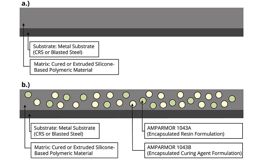
In this article, we discuss the design of self-healing functionality into silicone-based protective materials to improve their ability to maintain adhesion after damage. Specifically, we discuss the evaluation of the performance of AMPARMOR™ 1043, developed by Autonomic Materials, Inc. (AMI), in silicone-based coating and sealant formulations based on moisture-oxime-cured polydimethyl-siloxane (PDMS). AMPARMOR 1043 is a dual-capsule self-healing system comprised of AMPARMOR 1043A and AMPARMOR 1043B. Simply put, AMPARMOR 1043A and 1043B are comprised of microencapsulated formulations based on the resin and curing agents of a PDMS resin system based on hydrosilylation. For both coating and sealant applications evaluated, A and B capsules were added to the material in a 1:1 ratio. For example, a loading of 3 wt.% would include 1.5 wt.% of A and 1.5 wt. % of B. Damage to the coating or sealant incorporating AMPARMOR 1043 would rupture both A and B type capsules, releasing their contents into the site of damage where they would mix and react, initiating crosslinking of PDMS via hydrosilylation. Figure 1 shows a comparison of the control (Figure 1a) and self-healing (Figure 1b) configurations of the coating and sealant formulations evaluated.
Coating Evaluations
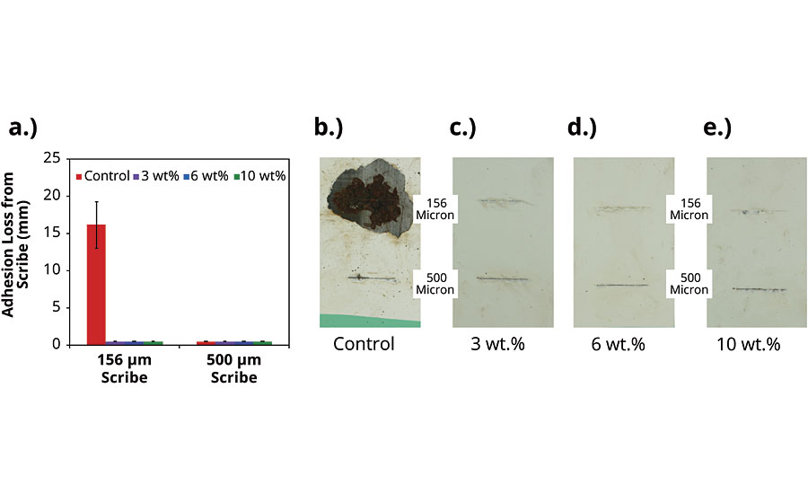
To evaluate the performance of AMPARMOR 1043 in the moisture-oxime-cured PDMS, a specified amount of part A and part B of the product was added to the coating and mixed in using a paddle mixer at roughly 1,000 RPM. A total of four disparate formulations including the control, which did not include any self-healing additive, and versions incorporating 3 wt.%, 6 wt.% and 10 wt.% were prepared and applied to lightly abraded cold-rolled steel (CRS) panels at dry film thicknesses of 450 to 500 microns. After curing at room temperature for 14 days, the coated panels were scribed using 156-micron and 500-micron scribe tools. After allowing the scribed panels to equilibrate at room temperature for 48 hrs, the panels were then exposed to a salt fog (ASTM B117) for a specified period of time. Figure 2a summarizes evaluations made after 300 hrs of salt fog exposure. While significant loss of adhesion and corresponding corrosion creep were observed around the 156-micron scribe for the control (Figure 2b), no loss of adhesion or corrosion creep were observed around either scribe for the panels coated with formulations incorporating AMPARMOR 1043 (Figures 2c-2e).
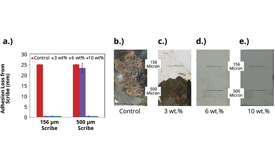
With longer salt fog exposure, a similar trend was observed (Figure 3a). Further loss of adhesion and corrosion creep were observed for the panels coated with the control for which practically no coating remained on the panels after 1,000 hrs of salt fog exposure (Figure 3b). This observation is consistent with the challenges with adhesion maintenance associated with silicone-based protective materials. Adhesion maintenance and germane corrosion resistance were observed to improve with the incorporation of AMPARMOR 1043. At a loading of 3 wt.%, adhesion loss and corrosion on the underlying substrate were observed only around the 500-micron scribe as opposed around both scribes, as was the case for the control (Figure 3c). At loadings of 6 wt.% and 10 wt.%, no adhesion loss or corrosion creep were observed around either scribe upon scraping the panels (Figures 3d and 3e).
The improvement in the coating’s performance as a function of the AMPARMOR 1043 loading was also confirmed via electrochemical impedance spectroscopy (EIS). EIS evaluations were performed on separate CRS substrates coated with the same formulations discussed above, including the control formulation and the versions incorporating AMPARMOR 1043 at loadings of 3 wt.%, 6 wt.% and 10 wt.%. To facilitate a quicker evaluation, the coating formulations were applied at a lower DFT range of 200 to 250 microns. The characterization was performed using a three-electrode electrochemical set-up in 3 wt.% NaCl solution and a VMP3 multichannel potentiostat (VMP3, Biologic, USA). A glass cylinder was affixed to the coated metal surface to be evaluated by a rubber O-ring clamped to the substrate and filled with 3 wt.% NaCl solution. The reference electrode (standard silver/silver chloride electrode) and counter electrode (platinum wire) were then inserted into the electrolyte solution. The working electrode was connected to the sample (coated metal substrate) to be tested. The total tested area was 7 cm2. The open circuit potential (OCP) was measured for 15 min to ensure that the system was stable and at equilibrium before making impedance measurements. Impedance measurements were carried out at OCP by applying a 10-mV sinusoidal voltage and varying the frequency from 0.1 Hz to 100 kHz. The coated panels were damaged using a 500µm scribe tool and allowed to equilibrate at room temperature for 48 hrs prior to making EIS measurements.
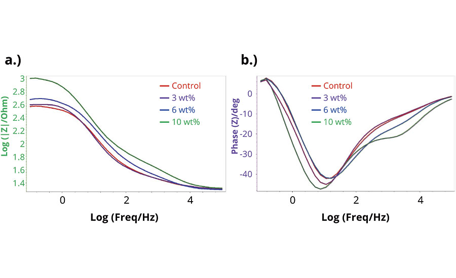
Resulting Bode impedance and Bode phase angle plots are shown in Figures 4a and 4b respectively. As shown in Figure 4a, the formulation incorporating 10 wt.% of AMPARMOR 1043 exhibited higher impedance relative to the control at all frequencies below 104 Hz; the formulation incorporating 6 wt.% exhibited higher impedance relative to the control at frequencies less than 103 Hz; and finally, the impedance of the formulation incorporating 3 wt.% tracked closely with the impedance of the control at all frequencies, exhibiting a slightly higher impedance relative to the control at frequencies less than 2.5 Hz. Impedance properties at higher frequencies are generally associated with pore resistance and coating capacitance of a coating close to the scribe. The impedance exhibited by the coating formulations incorporating 6 wt.% and 10 wt.% suggests that the incorporation of microcapsules and the release of healing agents from these capsules when a coating is damaged by scribing led to an improvement in the pore resistance of the coating close to the scribe as well as the corresponding coating capacitance of the coating. Further, impedance properties at lower frequencies can be correlated with double layer capacitance and charge-transfer resistance at the interface of the coated steel substrate and the electrolyte solution present within the scribe. As such, the increase in impedance relative to the control at 0.1 Hz observed with the incorporation of AMPARMOR 1043 microcapsules can be attributed to the improvement in corrosion resistance of the coating at the scribe. Phase angle data, shown in Figure 4b, is indicative of the degree of resistive and capacitive behavior of a coating. As illustrated in Figure 4b, all the coating formulations evaluated exhibited similar trends in phase angle measurements, with more resistive behavior observed at higher and lower frequencies, while more capacitive behavior was observed in the middle frequency region.
To further characterize the mechanism responsible for the improved adhesion maintenance and corrosion resistance observed for the coating formulations incorporating the microcapsules, cross-sections of a representative CRS panel coated with the control and one coated with a formulation incorporating 10 wt.% of AMPARMOR 1043 were evaluated by scanning electron microscopy (SEM). Images comparing both samples are provided in Figure 5. While the cross-section of the control exhibited a relatively smooth morphology (Figure 5a), ruptured capsules are visible in the cross-section of the coating containing the capsules (Figure 5b). The presence of ruptured capsules in the cross-section of the formulation incorporating AMPARMOR 1043 is further confirmation of a mechanism of improved corrosion resistance via healing agent release from the embedded capsules.

Sealant Evaluations
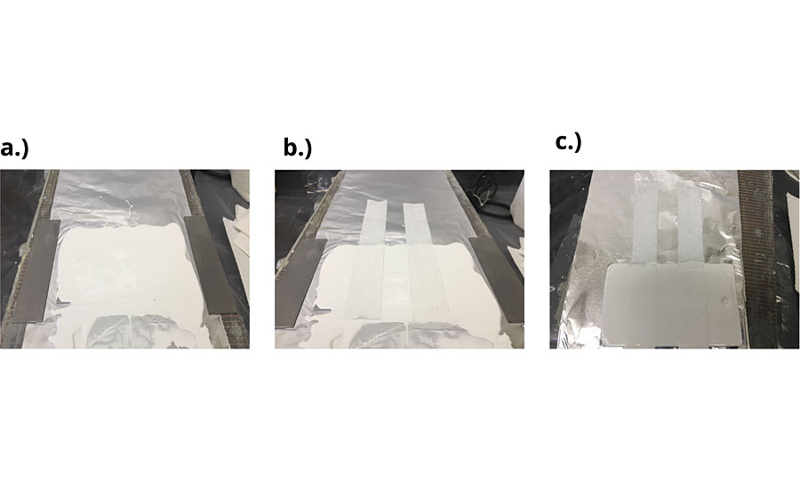
Similar evaluations were performed in sealant formulations based on the moisture-oxime-cured PDMS. For these evaluations, following ASTM C794 procedures, the sealant formulation was applied to clean CRS substrates, as shown in Figure 6. The first layer was applied to obtain 500-550 microns of wet film (Figure 6a). The ends of two 1-inch x 10-inch strips of low-profile fusion-bonded re‑inforcing polyester fiber mesh were placed on top of the wet film, 0.5 inches apart, along the 3-inch side of the 3-inch x 5-inch panels (Figure 6b). The final layer of the sealant was applied to obtain a total dry film thickness 1,000 to 1,100 microns (Figure 6c). The samples were allowed to cure at room temperature for 14 days.
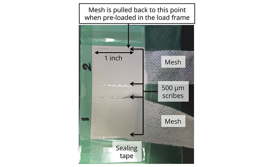
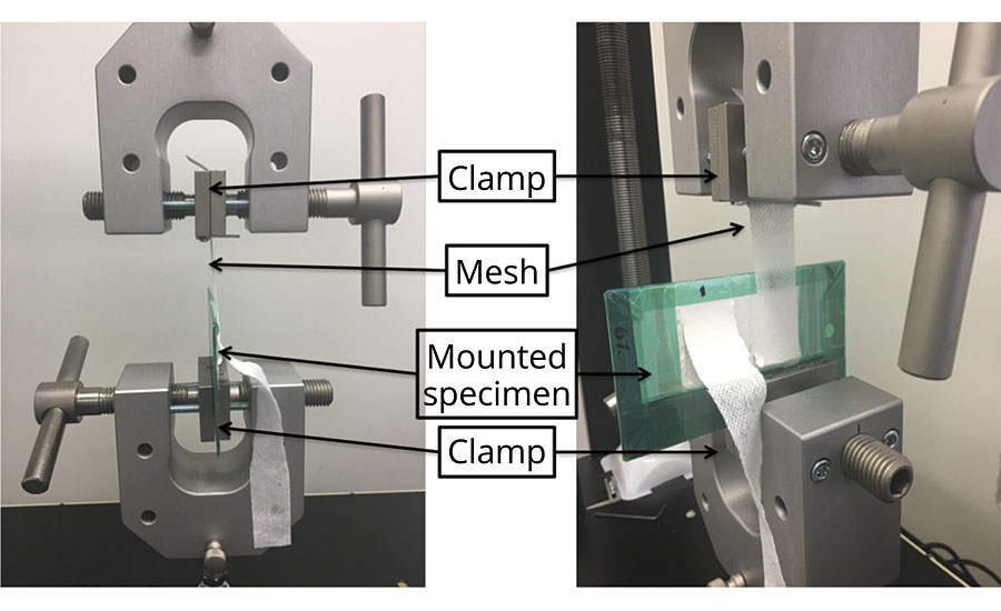
The sealant formulations evaluated included a control, which did not include any self-healing additives, and versions incorporating 3 wt.%, 6 wt.% and 10 wt.%. The peel strengths of the disparate sealant formulations were evaluated according to ASTM C794. The loose ends of the polyester mesh of the samples described above were bent back at 180º, and using a 500-micron scribe tool, the samples were damaged by cutting through the sealant, down to the substrate, along the edge of the mesh (Figure 7). Three sets of samples were evaluated. The peel strengths for the first set of samples were evaluated immediately after scribing, while the peel strengths for the remaining two sets of samples were evaluated after 500 hrs of salt fog exposure (ASTM B117) and 1,000 hrs of salt fog exposure respectively. To start the peel test, a small pre-cut was applied to the cured sealant to facilitate onset of the peeling process of the peel test. One set of the load frame grips was clamped onto the side containing the pre-cut. The other set of grips was clamped onto the mesh bent back at a180º angle with respect to the damaged area (Figure 8). The mesh was preloaded and pulled back up adjacent to the side of the scribes closest to the free end of the mesh. The mesh was peeled back at a rate of 50 mm/min along the 1-inch scribes. The peel strength for each mesh loaded was recorded as the average peel strength along the 1-inch section. Three panels, each with two polyester meshes, were tested for each type of formulation evaluated.
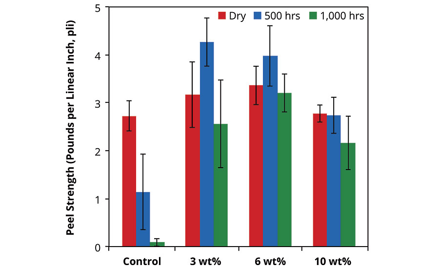
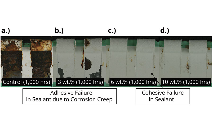
The peel strength results obtained for the sealant formulations evaluated are summarized in Figure 9. For the control sealant formulation, peel strength was observed to decrease with increasing salt fog exposure. These results are consistent with the observations made for the coating evaluations discussed above. Damage in the form of scribes made down to the substrate adjacent to the mesh created an entry point for the salt fog leading to corrosion at the sealant/substrate interface. As expected, corrosion at the sealant/substrate interface compromised the peel strength of the sealant, with longer exposure (1,000 hrs vs. 500 hrs) leading to a greater decrease in peel strength. An evaluation of the sealant samples after peel testing confirmed that while in the absence of salt fog exposure, the control exhibited cohesive failure in the silicone sealant (Figure 10a), after 1,000 hrs of salt fog exposure, the underlying CRS was significantly corroded, compromising the adhesion of the sealant to the substrate (Figure 11a). Sealant formulations incorporating 3 wt.%, 6 wt.% and 10 wt.% of AMPARMOR 1043 that were not exposed to ASTM B117 conditions all exhibited similar peel strengths to the control, suggesting that the incorporation of AMPARMOR 1043 into the sealant formulation was not deleterious to the peel strength of the sealant (Figure 9). Further, as also summarized in Figure 9, improved maintenance of peel strength was observed for the sealant formulations incorporating AMPARMOR 1043. Consistent with the peel strengths recorded for the sealant formulations incorporating AMPARMOR 1043, cohesive failure was observed in the corresponding samples evaluated following peel testing for the set of samples that were not exposed to ASTM B117 conditions (Figures 10b-d) as well as the samples exposed to ASTM B117 conditions for 1,000 hrs. The latter set of results is indicative of the benefit of the release and subsequent polymerization of the healing agents comprising AMPARMOR 1043 at the site of damage upon damaging the sealant via scribing.

Conclusions
Key takeaways from the work reported here include the following:
- The incorporation of AMPARMOR 1043 into coating and sealant formulations based on moisture-oxime-cured PDMS resulted in formulations with the ability to maintain adhesion to underlying CRS substrates after damage.
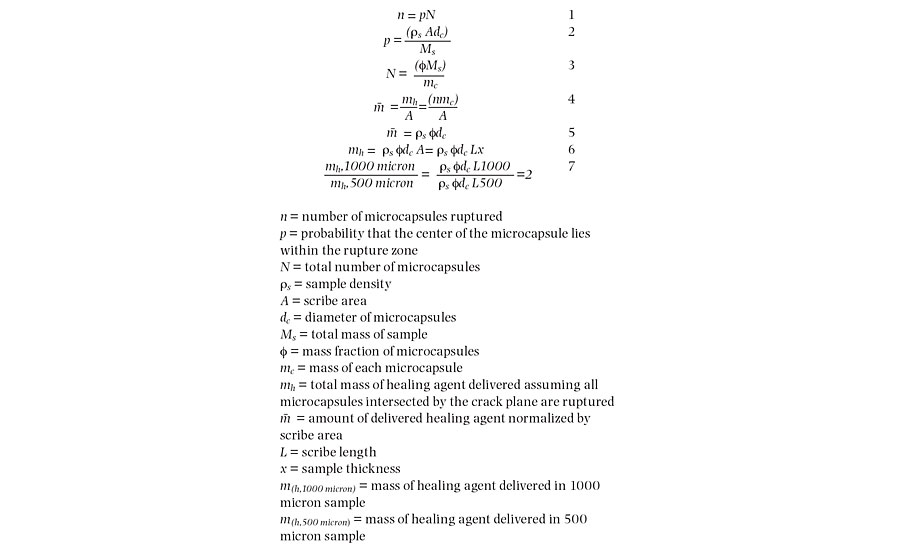
- To a significant extent, as assessed in salt fog exposure as well as via electrochemical methods, the self-healing performance or the ability of the coating to maintain adhesion to the underlying CRS substrates after damage was concentration dependent, as formulations incorporating 6 wt.% and 10 wt.% exhibited no loss of adhesion around the scribe made in the coated samples after 1,000 hrs of salt fog exposure. Sealant samples, which were at least 100% thicker relative to the coating samples, exhibited less concentration dependence between 3 wt.% and 10 wt.% of AMARMOR 1043 incorporated into the formulation. This observation likely is due to the increase in the amount (volume or mass) of healing agent deliverable at the site of damage in the thicker sealant relative to the coating.16 As illustrated in Equation 7 below, increasing the material (coating or sealant) thickness by a factor of 2 (500 microns to 1,000 microns) while keeping the mass fraction of microcapsules constant (for example at 3 wt.%) results in an increase in the amount of healing agent deliverable at the site of damage by a factor of 2. In other words, the amount of healing agent deliverable at the site of damage in a formulation containing 3 wt.% capsules and applied at a thickness of 1,000 microns is equivalent to the amount of healing deliverable at the site of damage in a formulation containing 6 wt.% capsules and applied at a thickness of 500 microns. The effect of material thickness on amount of healing agent deliverable at the site of damage is further elucidated below:
- The incorporation of up to 10 wt.% of AMPARMOR 1043 into the sealant formulation did not result in deleterious effects on the peel strength of the sealant prior to salt fog exposure.
- Finally, the demonstration of the self-healing functionality in the moisture-oxime-cured PDMS coating and sealant formulations discussed in this article suggests the potential of designing similar functionality into 2K RTV and extruded silicone-based materials with similar mechanical properties.
References
1 White, S.R.; Sottos, N.R.; Geubelle, P.H.; Moore, J.S.; Kessler, M.R.; Sriram, S.R.; Brown, E.N.; Viswanathan, S. Autonomic Healing of Polymer Composites, Nature, 2001, 409, 794-797.
2 Wilson, G.O.; Caruso, M.M.; Reimer, N.T.; White, S.R.; Sottos, N.R.; Moore, J.S. Evaluation of Ruthenium Catalysts for Ring Opening Metathesis Polymerization-Based Self-Healing Applications, Chemistry of Materials, 2008, 20, 3288-3297.
3 Wilson, G.O.; Caruso, M.M.; Schelkopf, S.R.; Sottos, N.R.; White, S.R.; Moore, J.S. Adhesion Promotion via Non-Covalent Interactions in Self-Healing Polymers, ACS Applied Materials Interface, 2011, 3, 3072-3077.
4 Kamphaus, J.M.; Rule, J.D.; Moore, J.S.; Sottos, N. R.; White, S. R. A New Self-Healing Epoxy with Tungsten (VI) Chloride Catalyst, Journal of Royal Society: Interface, 2008, 5, 95-103.
5 Caruso, M.M.; Delafuente, D.A.; Ho, V.; Moore, J.S.; Sottos, N.R.; White, S.R. Solvent-Promoted Self-Healing Materials, Macromolecules, 2007, 40, 8830-8832.
6 Caruso, M.M.; Blaiszik, B.J.; White, S.R.; Sottos, N.R.; Moore, J.S. Full Recovery of Fracture Toughness using a Non-Toxic Solvent-Based Self-Healing System, Advanced Functional Materials, 2008, 18, 1898-1904.
7 Gladman, A.S.; Celestine, A.D.N.; Sottos, N.R.; White, S.R. Autonomic Healing of Acrylic Bone Cement, Advanced Healthcare Materials, 2015, 4, 202-207.
8 Huang, M.; Yang, J. Facile Microencapsulation of HDI for Self-Healing Anti-Corrosion Coatings, Journal of Materials Chemistry, 2011, 21, 11123-11130.
9 Yang, J.; Keller, M.W.; White, S.R.; Sottos, N.R. Microencapsulation of Isocyanates for Self-Healing Polymers, Macromolecules, 2008, 41, 9650-9655.
10 Cho, S.H; White, S.R.; Braun, P.V. Self-Healing Polymer Coatings, Advanced Materials, 2009, 21, 645-649.
11 Keller, M.W.; White, S.R.; Sottos, N.R. A Self-Healing Poly(Dimethyl Siloxane) Elastomer, Advanced Functional Materials, 2007, 17, 2399-2404.
12 Caruso, M.M.; Silvia, A.W.; McIntire, P.J.; Wilson, G.O.; Sottos, N.R.; White, S.R.; Moore, J.S. A Self-Healing Biomaterial Based on Free-Radical Polymerization, Journal of Biomedical Materials Research Part A, 2014, 102, 3024-3032.
13 Kasisomayajula, S.; Dayton, C.R.; Wilson, G.O. The Next Generation of Zinc-Rich Primers: Improved Versatility and Performance via Self-Healing Functionality, Paint and Coatings Industry, March, 2019, 50-55.
14 Wilson, G.O.; Andersson, H.M. Self-Healing Systems for High-Performance Coatings, Paint and Coatings Industry, May, 2012, 58-60.
15 Wilson, G.O.; Ebbert, B.R.; Andersson, H.M. Improved Corrosion Resistance in Powder Coatings via Microencapsulated Self-Healing Agents, Paint and Coatings Industry, March, 2017, 49-59.
16 Rule, J.D.; Sottos, N.R.; White, S.R., Effect of Microcapsule Size on the Performance of Self-Healing Polymers, Polymer, 2007, 48, 3520-3529.
Looking for a reprint of this article?
From high-res PDFs to custom plaques, order your copy today!


