Pigments Exhibiting Diffractive Light Interference
The phenomenon of light interference can be produced using thin film or diffraction technology. Color-shifting pigments, ranging from micas to highly engineered, multi-layer pigment flakes, all based on thin film light interference, have been used in the marketplace for a number of years.
When diffractive light interference technology is employed instead of thin film light interference, a new family of effect pigments is produced. Diffractive pigments are prepared by vacuum deposition on a specially patterned surface and may be used to present a new variety of color effects.
A previous article in PCI (May 2002) introduced SpectraFlair® diffractive pigment. This article will further detail the design and manufacture of diffractive pigments, as well as provide optical, morphological and physical property test data.
Light Interference
If they are in phase, two parallel light beams of the same wavelength can interact with each other, creating a condition of reinforcement (constructive interference). In this case, the fields will combine, and as a result, a new single wave with double amplitude will be created. Total cancellation (destructive interference) will occur when two beams of the same amplitude are out of phase by a factor of one half wavelength (l/2). Other conditions of phase shifts and amplitudes will create intermediate results of interference. Following is a brief explanation of the phenomenon of light interference by thin film and diffraction.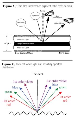
Thin Film Light Interference
To understand how this thin film light interference works, we must first look at the construction of one type of thin film pigment flake (Figure 1). The flake is made up of an opaque central reflecting core of aluminum, dielectric spacer layers in contact with both surfaces of the aluminum, and a semi-transparent, non-selective absorbing layer on the two exterior surfaces. The reflecting core, the spacer layers, and the absorber layers have no spectral peaks (that could give rise to color) across the entire visible electromagnetic spectrum. However, when placed in intimate contact with one another in the structure described, brilliant, high-chroma (high color saturation) pigment materials become possible. White light is broken down into its individual color components by selective destructive and constructive interference as the light reflects off interfaces on either side of the reflector. Only certain wavelengths are absorbed because the spacer layer dictates which wavelengths reach the semi-transparent absorber layer at maximum field. It is the path length (the distance that light travels through the glass-like layer) difference that dictates which wavelengths are reflected to the eye.
Hue, the color of the pigment, is primarily determined by the physical thickness of the spacer layer, i.e. it is dependent on which wavelengths were designed for maximum interference. Chroma, on the other hand, is determined by a combination of the absorber layer and the spacer layer selected. The degree of saturation for a particular color is a direct result of the absorber layer absorbing specific wavelengths and the influence of the highly reflective aluminum layer.
Diffractive Light Interference
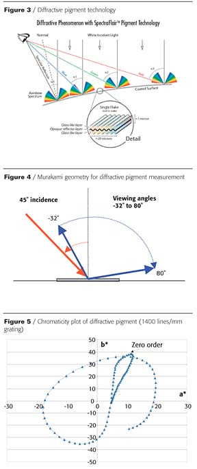
Diffraction occurs when light waves encounter an obstacle of dimensions similar to their wavelength. Examples: light passing by the edges of an opaque body, through narrow slits or it being reflected from a ruled surface.A diffraction grating can be defined as an optical component made by a periodic assembly of reflecting or transmitting obstacles (grooves) separated by a distance comparable to the wavelength of light applied. Diffraction gratings are used to disperse a beam of white light into its component wavelengths, producing a spectrum (Figure 2).
There are basically two types of diffraction gratings (ruled and holographic). In the case of ruled gratings, various shapes, such as triangular symmetrical, triangular blazed, square-wave with different top plateau sizes, and sinusoidal gratings, can be produced. Additionally, a variety of groove frequencies, blazed angles and depth profiles can be produced. For a given grating frequency, the depth, shape and orientation of the grooves determine the relative intensity of the various orders.
Diffraction Of Light By A Grating
When light is incident on a grating, it is diffracted into discrete wavelengths. The incident beam is separated, forming the zero order diffraction, or specular reflection, that is a mirror-effect color of the incident light. First order diffractions (-1st order and 1st order) surround the zero order. Eventually, other higher orders surround the first orders depending on the groove frequency of the grating.The property of grating to diffract light is described by the grating equation:
ml = d(sin a + sin b)
where a and b are the angles between incident light and normal and diffracted beam and the normal to the grating respectively; m is an integer called the diffraction order. For m = 0, b = - a for all l, the wavelengths are not separated; this is the specular reflection or zero order.
The higher the groove frequency, the greater will be the angular separation between orders. The size of a grating will improve the definition of the various orders (resolving power) as adjacent spectral lines are clearly separated. Finally, for a given grating frequency, the depth, shape and orientation of the grooves determine the relative intensity of the various orders.
Diffractive Pigment Development
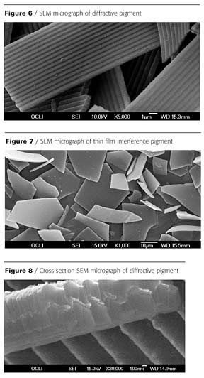
Diffractive effects are based on flakes with a microstructure resolution within the wavelengths of visible light (Figure 3). There are many demonstrations of diffractive optical effects in non-flake form, notably linear diffractive gratings on plastic or metal foils and holograms. Linear diffractive gratings are repetitive structures made of lines or grooves in a material to form a peak-and-valley structure (hundreds or thousands of lines per millimeter). Desirable optical effects within the visible spectrum occur when diffraction gratings have regularly spaced grooves at uniform depths on a reflective surface. Diffractive surfaces perform better with directional illumination in order to see the color effect.Initially, experimental pigment was produced in a conventional box coater vacuum chamber. The influence of the grating frequency, groove shape and depth were studied during this phase of development. The optical appearance of the pigment strongly depends upon the diffractive efficiencies of the zero and higher orders. The efficiency of the different orders is accomplished by the selection of the groove depth, shape and frequencies of the foil substrate grating.
Once the optimum set of variables was established, larger prototype runs of diffractive pigment were produced using a large, production-scale vacuum roll coater. Samples prepared from the prototype testing were used to determine the optimum particle size and to establish pigment-loading formulations. Samples were also prepared for durability and physical property testing.
Optical Properties
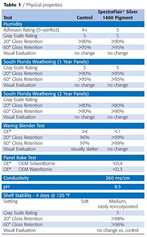
Samples were prepared for optical measurements by first incorporating the pigment into a clear, organic binder and then drawing down the pigment mixture onto black/white coated card stock to yield a continuous film of randomly oriented pigment flakes that exhibit good leafing. Only the black portion of the coated card was used for characterization to prevent any measurement errors that would occur due to non-uniform pigmented drawdowns.The color performance of these samples, under direct illumination, was characterized using a gonio-spectrophotometer (Murakami Color Research Labs.) This instrument was capable of measuring color under a variety of different illumination and viewing angles. Figure 4 shows the illumination geometry chosen to characterize the samples: 45° incidence angle, -32 to 80° receiving angle in 2-degree steps. An illumination angle of 45° was chosen because most of the diffractive color orders for the grating frequencies selected are present for this geometry. Also, this angle represented the most common viewing geometry for visual evaluations. Receiving angles lower than -32° were excluded due to a discontinuity on the measurements caused by the illumination source blocking the detector. The Murakami instrument also provided data corresponding to 1979 CIELab color coordinates based on a D65 illumination and 10° observer. This instrument was calibrated on a diffuse white tile using a 45°/0° measurement geometry.
Each diffraction order reflected from a grating contains all the wavelengths of the visible light. When the detector scanned a particular diffraction order, it was detecting the entire visible spectrum. The a*b* chromaticity diagram of a 1400 lines/mm frequency grating (Figure 5) was used here to illustrate this effect. For this pigment design, only the 1st diffraction order was visible.
Depending upon the illumination and measurement angle, the spectrophotometer measured a different portion of the spectrum generated by the light reflected from the diffractive pigment. In effect, when the detector scanned from -32 to 80 degrees, it saw the entire visible spectrum creating a full color travel in the resulting a*b* diagram. As shown in Figure 5, the 1st order formed a complete circle, indicating the entire color spectrum was visible. The semi-straight line where a* and b* changed monotonically corresponded to the zero order diffraction (specular reflection).
Under diffuse illumination, the color performance was also characterized using a DataColor SF600+ spectrophotometer. This instrument used an integrating sphere to yield a diffuse/8-degree illumination/viewing geometry with specular included. These instruments were complementary in our study in the sense that for diffractive pigments, the data obtained with the gonio-spectrophotometer simulated the optical behavior under direct illumination, similar to viewing the samples under a bright sun. In comparison, the DataColor data simulated the optical behavior of the samples under cloudy conditions.
Morphological Properties
Diffractive pigment was a unique material consisting of an ultra-thin textured pigment in the form of micron-size flakes with an average aspect ratio of 20:1. The pigment was opaque, thin, highly specular (mirror-like) and exhibited a rainbow-like diffraction effect.Diffractive pigments were produced by depositing a three-layer-thin film stack of magnesium fluoride (MgF2)/aluminum (Al)/magnesium fluoride (MgF2). This three-layer stack and microstructure created a pigment with a bright silver metallic coloration when illuminated under diffuse lighting conditions and strong iridescent diffractive effects under direct illumination. The magnesium fluoride layers did not play an optical role, but provide rigidity and environmental protection to the opaque, reflecting aluminum layer.
Scanning Electron Microscopy (SEM) was used to characterize the morphology and microstructure of the pigments. While flake size dimensions and thicknesses were basically similar between the thin film interference pigment and the diffractive pigment, the diffractive pigments exhibited a controlled surface microstructure (Figure 6) in contrast to flat thin film interference pigments (Figure 7). Cross-section SEM micrograph (Figure 8) further detailed the pigment microstructure and illustrate the grating structure of the pigment.
The diffractive pigment particle size distribution was obtained using a Horiba 300 Laser Scattering instrument. The median particle size in volume (D50) averaged 20 mm (+/- 2 mm). The thickness of the pigment flakes was targeted to be 1 mm. The platelet-like morphology and high aspect ratios (greater than 20:1) of the pigment resulted in excellent orientation properties in application.
Physical Properties
High-performance protective coatings are used to extend the useful life of many products. The purpose of durability testing is to predict long-term performance of the coating in the service environment. Durability tests are designed to be more intense in exposure and duration than those conditions normally encountered in the service life of the coating. Coatings containing SpectraFlair pigment are being evaluated in a variety of tests simulating environmental exposure, circulation resistance and shelf stability.Humidity
Panels are prepared in standard automotive solventborne basecoat/clearcoat paint systems. Panels are placed in a humidity chamber set for 102 °F +/- 2 °F and 93% +/- 2% relative humidity (RH) for a period of 96 hours. Panels are allowed to recover at ambient conditions for 10 minutes.
Adhesion is tested prior to exposure in the humidity chamber and after the 10-minute recovery according to ASTM D 3359. Color, gloss and appearance are also evaluated per the specified measurement methods. Test results are summarized in Table 1.
Accelerated Weathering
Panels are prepared in standard automotive solventborne basecoat/clearcoat paint systems. The panels are exposed in masstone and as a 5% carbon black: 5% aluminum: 90% SpectraFlair pigment blend. The test chamber lamp is equipped with a quartz inner filter and a borosilicate outer filter. Color, gloss and appearance are evaluated per specified methods.South Florida Weathering
Panels are prepared in standard automotive solventborne basecoat/clearcoat paint systems. The panels are exposed in masstone and as a 5% carbon black: 5% aluminum: 90% SpectraFlair pigment blend. The one-year exposure panels are prepared at both 1⁄2 film build clearcoat and full film build clearcoat. Two- and four-year panels are prepared at full clearcoat film build.
All panels are exposed at an angle of 5° from the horizontal and facing the equator (i.e. 5° south black box) at a Miami, FL, test facility. Two-year exposure panel results are currently available.
Circulation Resistance
The pigment is incorporated into a standard automotive solventborne paint system. The paint sample is then adjusted to the correct application viscosity. The sample is divided into two equal aliquots. One sample is blended at 21,000 RPM for eight minutes in the test apparatus. The equipment is water jacketed to maintain temperature below 110 °F. The remaining sample is stored at ambient conditions. After the completion of the test, the blended sample is allowed to recover for 24 hours at room temperature.
Panels are prepared with both the blended sample and the control sample. Color, gloss and appearance are evaluated. Table 1 provides a summary of results.
Shelf Stability
The pigment sample is incorporated into standard automotive solventborne and waterborne basecoat systems. The paints are then adjusted to the correct application viscosity. The sample is divided into three equal aliquots; each is placed in a steel container and sealed. One sample is placed in 140 °F oven for 16 hours, the second is placed in a 120 °F oven for four days and the third is stored at ambient conditions.
After the completion of the test, the samples are allowed to cool room at temperature. The cans are opened and the level of settling in each can is evaluated using a spatula. Painted panels are prepared from all samples. CIE ∆E* color values are generated using the samples stored at room temperature as the control. The results are summarized in Table 1.
Pigment Application
The color effect produced by this pigment is generated by the diffraction of light waves due to the material's uniquely textured surface. The diffractive effect of the pigment depends on the interaction of light with the pigment surface. Due to the high flake-diameter-to-thickness ratio, diffractive pigments exhibit good leafing properties, thus creating a high level of specular reflection. The pigment is basically a neutral color that may be used as the sole colorant or combined following additive color theory with other pigments and dyes to create custom color stylings.
Relatively low loadings of 2-6%, based on total formula weight, are needed to produce a dramatic color effect; amounts may vary depending on the addition of other conventional pigments. Diffractive pigment is readily dispersible in most vehicle systems. The pigment is easy to use and is often referred to as a "stir in" pigment and is compatible in a wide range of standard formulations.
Summary
Basic concepts of diffraction grating theory, together with principles of platelet-like pigments, were taken into consideration when creating of this new family of pigments. The optical properties of these pigments are based on optical interference by diffraction instead of thin film optical interference used on traditional optical variable pigments.By controlling the physical dimensions and surface microstructure, diffractive pigment generates the appearance of multiple, bright rainbow-producing prisms moving over a liquid silver color. The effect is pleasing, elegant and exhibits dramatic visual appeal that is unique, durable and easy to incorporate. Diffractive pigment opens new worlds of design possibilities and adds value and appeal to virtually any product..
Acknowledgements
The author wishes to thank the many Flex Products colleagues whose knowledge and experience made this paper possible. Special thanks for their support go to Alberto Argoitia, Product Development; Sean Chu and Mike Nofi, Test Method Development; Matt Witzman, Manufacturing; PAL Technical Staff, Physical Property Testing and Application; and Mary Ellen King and Bob Matsuba, Photos and Graphics.
References
1. Argoitia, A. and Witzman, M. Proceedings of the 45th Annual Technical Conference, Soc. Vac. Coaters, April 13-18, 2002.
2. Argoitia, A. Proceedings of Fall 2002 AIMCAL Conference.
Phillips, R.W. "Optically Variable Films, Pigments and Foils", SPIE Vol. 1323
3. Optical Thin Films III: New Developments, 98, 1990.
4. Loewen, E.G. and Popov, E. Diffraction Gratings and Applications, 1997.
5. Hutley, M.C. Diffraction Gratings, 1982.
6. Argoitia, A. and Bradley Jr., R.A. Diffractive Pigment Flakes and Composition, Patent Pending, Docket No. 13676.176, 2001.
Looking for a reprint of this article?
From high-res PDFs to custom plaques, order your copy today!


