Eight Things You Probably Don’t Know About the Electric Heaters in Your Fluid Dispensing System – Part II
yacobchuk, iStock/Getty Images Plus, via Getty Images
In Part 1 of this two-part series, we addressed four little known flaws in common electric heating approaches that could be causing failures in your fluid dispensing system instead of addressing the problems you set out to solve. These included the issue with the underlying logic on which most electric heating systems are based, the lack of cooling in these systems, how placement of the heaters affects performance, and the disconnect between the heater temperature and the application temperature.
In this final segment, we tackle four more issues you may be facing — things that you may not even realize are causing you problems!
5. Viscosity Variations Affect Your Spray Pattern
In spray application systems, temperature-based viscosity variations directly affect the shape and integrity of the fan pattern being dispensed. Since that’s often construed as a bold statement, a little proof is in order. Figure 7 shows the results of a controlled experiment in which a robotic system was used to repeat the gun path, speed, and angle and distance to the part to spray each of the coupons with a fixed orifice gun under constant pressure. The only thing that was varied was the temperature of the coating, which, of course changed the viscosity of the coating being sent to the nozzle.
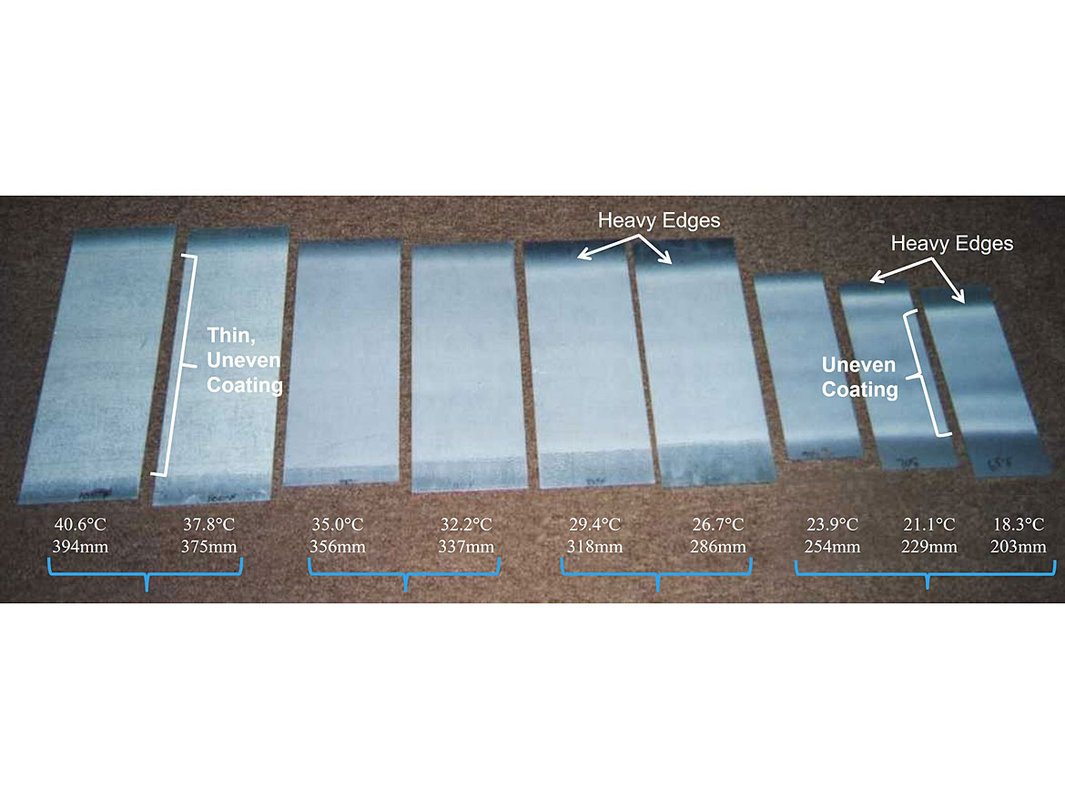
The most obvious change is in the width of the fan pattern. But perhaps less obvious, yet even more important, is the impact of viscosity on spray consistency.
Above 35 °C (left two coupons), the coating is thin and uneven. You can see the substrate peeking through. Even if it adheres well, it can’t do its job. By contrast, in the 30 °C to 35 °C range the coating is smooth and even from edge to edge. This is the optimal operating temperature (read: viscosity) for this particular process.
Below 30 °C (due to the increased viscosity) we see heavy edges beginning to appear. These are often associated with “striping” on the finished part. And continuing into the 25 °C range and below, we see the combination of very uneven coating surrounded by heavy edges, which makes it virtually impossible to get a smooth, even coating on the finished part — whether you’re painting manually or with a robot. Without a smooth, even coating, both performance and appearance will be compromised.
6. Gaps in the System Create Unpredictability
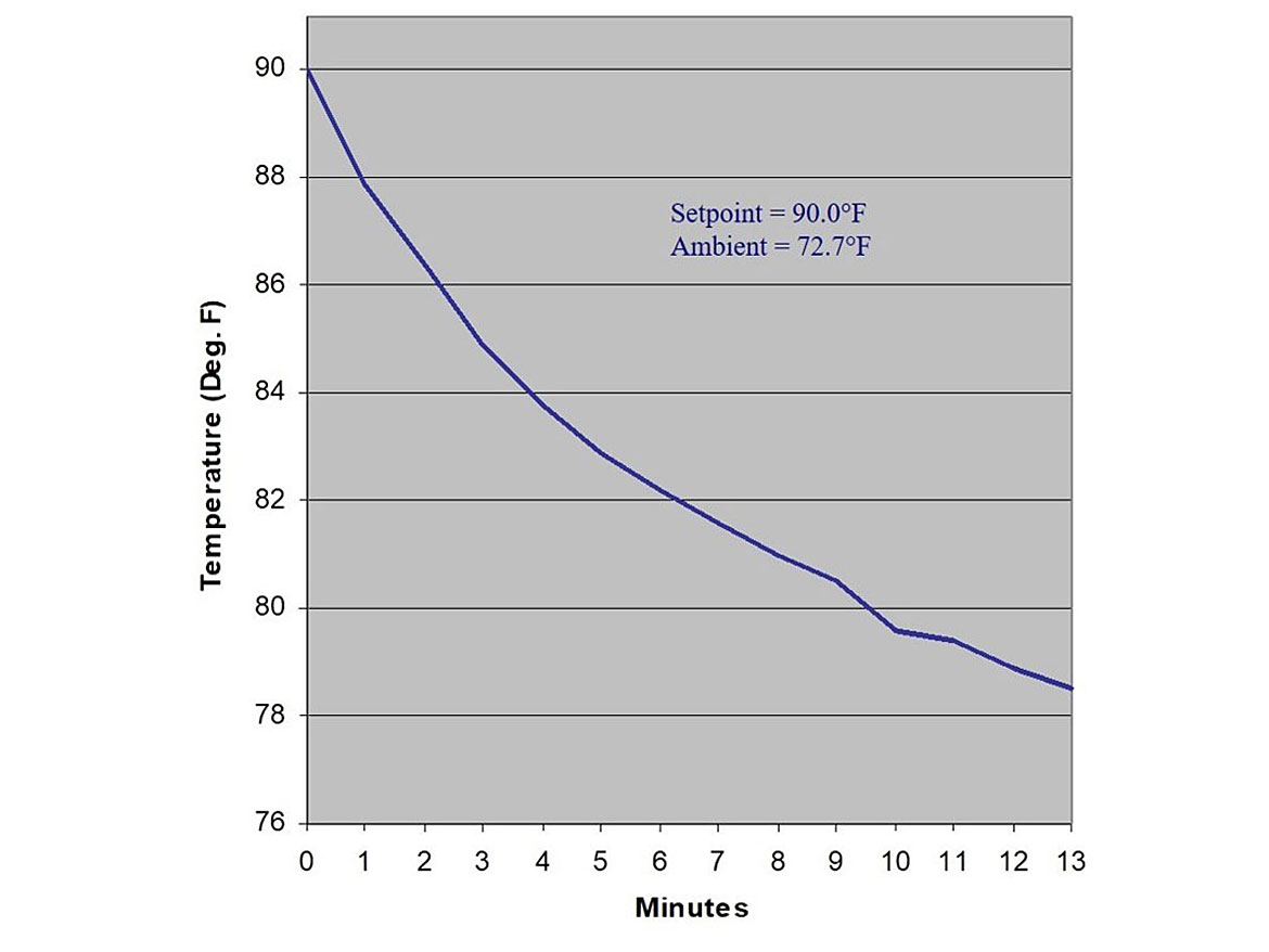
As if spray consistency wasn’t enough, the importance of this behavior becomes even more apparent when we examine the impact of gaps in our 90 °F temperature control envelope that allow ambient to affect our coating material. Figure 8 shows the effect of a 73 °F ambient on a stainless-steel gun, when the spray stops — like during a break or lunch, or downtime event. It’s OK when we are processing and the material is in constant motion, but when we stop, the temperature of the valve falls toward ambient and the viscosity of the material increases, which drives a change in spray pattern as we saw in Figure 7.
Figure 9 shows the impact that this change in temperature (and in turn viscosity) has on the dispense pattern, which can be completely anticipated from Figure 7. As the colder (71 °F) material in the gun is dispensed, the pattern is narrower and heavier, but as the warmer material (85 °F) reaches the gun, the lower viscosity causes the pattern to widen and the coverage to thin. This could just as easily have been a fitting anywhere in the delivery train creating a slug of off-viscosity material and creating a defect that may, or may not, get caught.
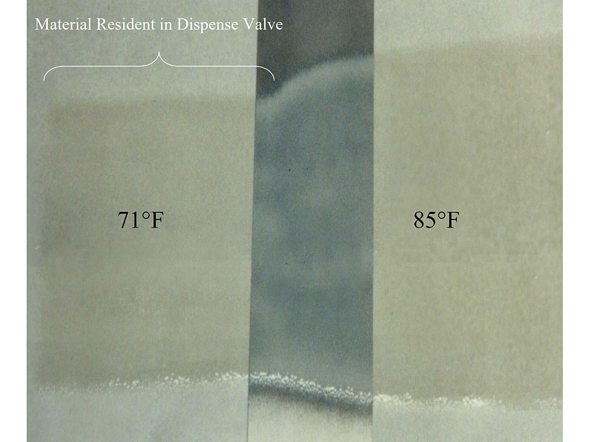
This is just one of the reasons that distance between the heat source and the applicator nozzle is of utmost importance to our process outcomes.
7. Remote Heating Dissipates Faster Than You Think
In Part 1 of this series, we introduced a thermal model that showed how the temperature of the coating changes as it flows through the delivery system to the point-of-application (see Part 1, Figure 4). The change is pretty dramatic, and often we get asked if the temperature of the coating really changes significantly between the heater and the point of application. In that segment, we also introduced a couple of good examples of in-line heater applications (Part 1, Figures 5 and 6). A deeper dive into those applications really drives the point home.
Figure 10 below shows an in-line heater mounted on the outside of the booth wall in the left frame, with a thermal scan of that heater in the right frame. There is much to be observed in the thermal scan. The inlet hose in the lower left corner shows that the coating is coming in at about 87 °F (Sp1), and by the time it leaves the 115 °F heater (Sp2) it is up to nearly 107 °F (Sp3). All good so far, but this is where devices in the path and the effect of ambient come into play. We can see from the scale that the ambient is approximately 80 °F.
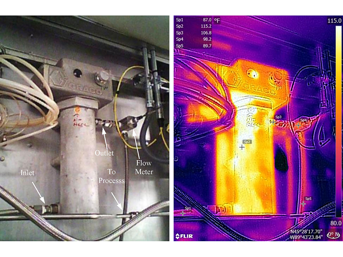
The surface area and thermal mass of the flow meter are the first things the coating encounters. Here we see it drop to roughly 98 °F (Sp4), and as it travels through the hose toward the booth interior it drops further to roughly 90 °F (Sp5).
Since thermal imaging shows only surface temperatures, the actual coating temperature at each of these points will be higher than the reading shown. The relative magnitude of the change, however, will be exactly as indicated.
Figure 11 shows the thermal scan of the 2K paint system introduced in the first segment of this article (see Part 1, Figure 5).
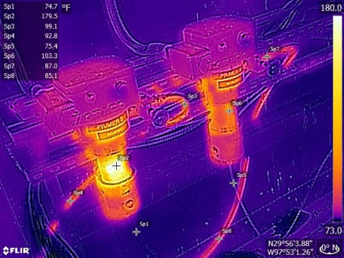
In the legend in the top left corner of the figure, we can see that the A and B coating components are entering the heaters at roughly 75 °F (Sp1 and Sp5). This makes sense in that they are both coming from the same ambient location, which is carefully controlled at 75 °F. It is here that things run amuck. It is clear that the left heater (Part B), at 179 °F (Sp2), is significantly warmer than the right heater (Part A) at 103 °F (Sp6). As expected, the outlet of Part B is about 99 °F (Sp3), whereas the outlet of Part A is lower, at 87 °F (Sp7).
Again, we see the coating components losing temperature as they move through the hoses with Part B at 93 °F (Sp4) and Part A at 85 °F (Sp8) roughly equidistant from each heater. As we can see in Figure 12, this loss continues along the path through the booth ambient with Part B at 87 °F (Sp4) and Part A at 82.5 °F (Sp5). These are getting closer to the ambient temperature, and the difference between them is shrinking due to the different rate of loss based on the temperature differential to ambient for each component. As with the previous example, the coating components are reaching the robot very near ambient — again, as if there were no heaters in the circuit at all.
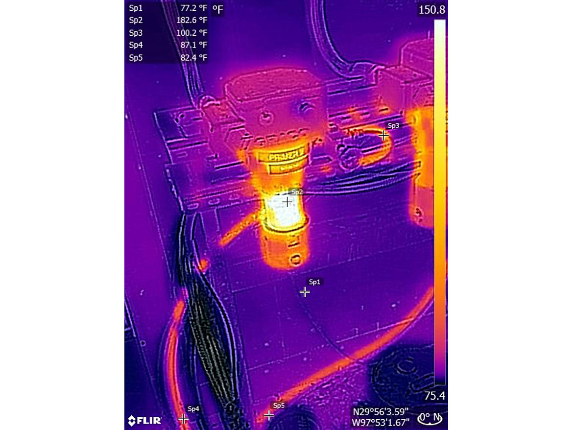
These examples suggest that the model we introduced (Part 1, Figure 4) is reasonably accurate.
8. Electric Heating Can Actually Damage Your Expensive Coating
But worst of all is the little-known fact that in the process of bringing the coating to the target temperature, electric heaters can actually damage the coating before it is even applied.
So how can a device designed to help with the process do damage?
The answer is “surface area". An electric heater is basically a heat exchanger, and there are two important factors that determine the magnitude of heat transfer — surface area and temperature differential (ΔT). Because in-line electric heaters have a very small surface area in contact with the coating, they must get very hot to heat the coating to the desired temperature — as shown in Figures 10 and 11. These hot surfaces can damage the coating, causing premature crosslinking, chemical separation, etc. This can result in agglomeration that clogs nozzles and filters, curing issues, poor adhesion, unacceptable appearance and a host of other problems.
Conclusion
From the data presented in these two segments, it’s clear that, though common in their implementation, there are many issues with in-line electric heaters that must be understood and managed if you are going to get stable, predictable performance out of your coating application system.
References
4 Electrically Heated 2K Paint System Photos courtesy of CFAN – San Marcos, TX. (Note: This has since been replaced with a modern heat/cool system.)
5 Source withheld by request.
6 Impact of Temperature Based Viscosity Variations on Spray Pattern data provided courtesy of Saint Clair Systems, Inc.
7 Impact of Ambient on Gun Temperature and Spray Pattern data provided courtesy of Saint Clair Systems, Inc.
Looking for a reprint of this article?
From high-res PDFs to custom plaques, order your copy today!


